UPS Installation Plan and Unpacking
3-6
Eaton 9EHD UPS (80-200 kVA, 380/400/415V) Installation and Operation Manual
•
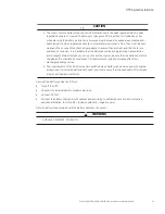
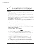
Refer to national and local electrical codes for acceptable external wiring practices.
•
To allow for future kVA upgrades, consider installing a derated UPS using wiring and external overcurrent
protection breakers sized for a fully rated UPS.
•
For external wiring, use 90°C copper wire. Wire sizes listed in Table 3-5 are for copper wiring only. If wire is
run in an ambient temperature greater than 30°C, higher temperature wire and/or larger size wire may be
necessary. Wire sizes are based on using the specified breakers.
•
Material and labour for external wiring requirements are to be supplied by designated personnel.
•
If installing an external maintenance bypass, all feeds to the UPS including the Rectifier Input Breaker (RIB) (if
installed) must have a service disconnect independent of the maintenance bypass power path. Most
maintenance bypass solutions provide UPS input feeds derived from but isolated from the maintenance
bypass power path. If the maintenance bypass solution being installed does not provide such functionality,
DO NOT use a single feeder breaker to supply both the UPS and the maintenance bypass.
•
The bypass feed into this equipment uses four wires (three line conductors and neutral conductor), plus
grounding conductor (protective earthing conductor) . The rectifier feed into this equipment uses four wires
(three line conductors and neutral conductor), plus grounding conductor (protective earthing conductor). The
phases must be symmetrical about ground (from a Wye/Star source) for proper equipment operation.
•
Parallel UPS input wiring size requirements and output wiring size requirements from the UPSs to the Tie
Cabinet are the sames as those for single systems.
•
This device is not equipped with its own mains separation device. It is , therefore, essential that the customer
install such a device at the installation site near the UPS.
•
Install a proper three-pole overcurrent disconnect device before connecting to the UPS, the disconnect
device shall disconnect simultaneously all line conductors of the AC MAINS SUPPLY.
•
Do not disconnect neutral, neutral required for system operation.
•
If a disconnect device interrupts the neutral conductor, it shall simultaneously interrupt all line conductors.
•
When single-phase current exceeds 100A, switches of protective atmosphere should be equipped with
arc-control device.
•
The UPS requires an input neutral connection. Ensure that an input neutral is connected prior to energising
the UPS. If a 4 pole Automatic Transfer Switch is installed upstream of the UPS it must work with a break
before make transition with a minimum transfer time of 50ms.
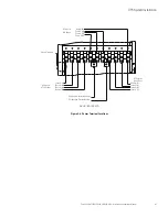
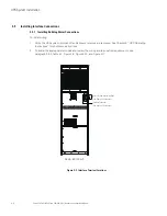
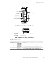
Figure 4-6 and Figure 4-7 show the location of the UPS power cable terminals.
CAPACITORS INSIDE
REQUIRE 5 MINUTES
TO DISCHARGE
TO A SAFE LEVEL
AFTER ALL POWER
IS REMOVED.
SEE HANDBOOK
FOR INSTRUCTIONS.
Summary of Contents for 9EHD Series
Page 81: ......
Page 82: ...614 0 00...


