background image

Eaton 9PX Lithium-Ion

P-164001006—Rev 01

41

C

Chhaapptteerr 88 S

Sppeecciiffiiccaattiioonnss

88..11

M

Mooddeell S

Sppeecciiffiiccaattiioonnss

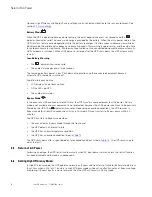
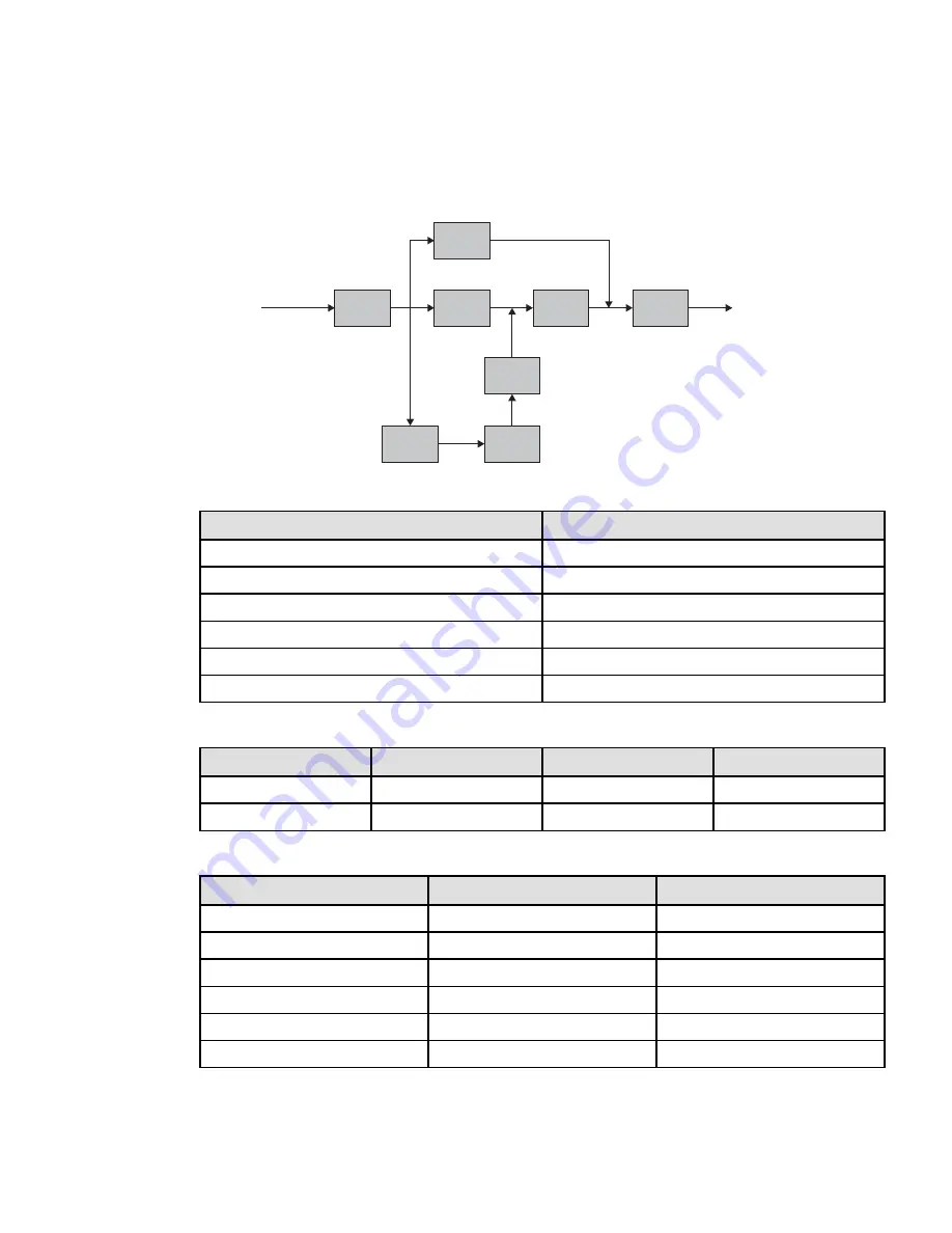
Input
Filter

AC/DC

Boost

DC/AC

Inverter

Outpout

Filter

Bypass

DC/DC

Battery

Charger

Table 7. Power Module List

Model

Power ratings

9PX1500RT-L

1500VA / 1350W

9PX2000RT-L

2000VA / 1800W

9PX3000RT-L

3000VA / 2400W

9PX1500GRT-L

1500VA / 1350W

9PX2200GRT-L

2200VA / 2000W

9PX3000GRT-L

3000VA / 2400W

Table 8. Extended Battery Module List

Model

Configuration

Battery Voltage

For Power Module

9PXEBM48RT-L

Rack / Tower

48Vdc

1500VA

9PXEBM72RT-L

Rack / Tower

72Vdc

2000 – 2200 – 3000VA

Table 9. Weights and Dimensions

Model

Dimensions D x W x H(inch/mm)

Weight (lb / kg)

9PX1500RT-L

17.7 x 17.3 x 3.4 / 450 x 440 x 86.5

35.5 / 16.2

9PX2000RT-L

23.8 x 17.3 x 3.4 / 605 x 440 x 86.5

50.6 / 23.0

9PX3000RT-L

23.8 x 17.3 x 3.4 / 605 x 440 x 86.5

52.7 / 24.0

9PX1500GRT-L

17.7 x 17.3 x 3.4 / 450 x 440 x 86.5

34.8 / 15.8

9PX2200GRT-L

23.8 x 17.3 x 3.4 / 605 x 440 x 86.5

48.6 / 22.1

9PX3000GRT-L

23.8 x 17.3 x 3.4 / 605 x 440 x 86.5

50.2 / 22.8

Summary of Contents for 9PX

Page 1: ...p n P 164001006 Revision 01 Eaton 9PX Lithium Ion Advanced Users Guide 9PX1500RT L 9PX2200RT L 9PX3000RT L 9PX1500GRT L 9PX2200GRT L 9PX3000GRT L 9PXEBM48RT L 9PXEBM72RT L Eaton 9PX Lithium Ion ...

Page 2: ...SK OF ELECTRIC SHOCK Observe the warning associated with the risk of electric shock symbol CAUTION REFER TO OPERATOR S MANUAL Refer to your operator s manual for additional information such as important operating and maintenance instructions This symbol indicates that you should not discard the UPS or the UPS batteries in the trash This product contains sealed lead acid batteries and must be dispo...

Page 3: ...trical shock The likelihood of such shock can be reduced if such grounds are removed during installation and maintenance applicable to equipment and remote battery supplies not having a grounded supply circuit Product Safety To connect the UPS instructions and operation described in the manual must be followed in the indicated order CAUTION To reduce the risk of fire the unit connects only to a ci...

Page 4: ... less than 25 C This charges the battery thus avoiding possible irreversible damage During the replacement of the Battery Module it is imperative to use the same type and number of element as the original Battery Module provided with the UPS to maintain an identical level of performance and safety If there are any questions don t hesitate to contact your local EATON representative All repairs and ...

Page 5: ...on 16 3 5 Rack Installation 17 3 6 Connecting the EBM s 18 3 7 Detecting other Accessories 19 3 8 UPS Connection without Hotswap MBP Module 20 3 9 Connection with a Hotswap MBP Module Optional Accessory 21 4 4 C Co om mm mu un niic ca at tiio on n 2 23 3 4 1 Communication Ports 23 4 2 UPS Remote Control Functions 24 5 5 O Op pe er ra at tiio on n 2 29 9 5 1 Start up and Normal Operation 29 5 2 Sta...

Page 6: ...wap MBP 35 6 4 Recycling The Used Equipment 35 7 7 T Tr ro ou ub blle es sh ho oo ot tiin ng g 3 37 7 7 1 Typical Alarms and Faults 37 7 2 Silencing the Alarm 38 7 3 Service and Support 38 7 4 CE Compliance Contact 39 8 8 S Sp pe ec ciif fiic ca at tiio on ns s 4 41 1 8 1 Model Specifications 41 Table of Contents ...

Page 7: ...ON has implemented an environmental protection policy Products are developed according to an eco design approach Substances This product does not contain CFCs HCFCs or asbestos Packing To improve waste treatment and facilitate recycling separate the various packing components The cardboard we use comprises over 50 of recycled cardboard Sacks and bags are made of polyethylene Packing materials are ...

Page 8: ... can be erratic These power problems have the potential to corrupt critical data destroy unsaved work sessions and damage hardware causing hours of lost productivity and expensive repairs With the Eaton 9PX you can safely eliminate the effects of power disturbances and guard the integrity of your equipment Providing outstanding performance and reliability the Eaton 9PX s unique benefits include Tr...

Page 9: ...D x W x H inch mm Weight lb kg 9PX1500RT L 17 7 x 17 3 x 3 4 450 x 440 x 86 5 35 5 16 2 9PX2000RT L 23 8 x 17 3 x 3 4 605 x 440 x 86 5 50 6 23 0 9PX3000RT L 23 8 x 17 3 x 3 4 605 x 440 x 86 5 52 7 24 0 9PX1500GRT L 17 7 x 17 3 x 3 4 450 x 440 x 86 5 34 8 15 8 9PX2200GRT L 23 8 x 17 3 x 3 4 605 x 440 x 86 5 48 6 22 1 9PX3000GRT L 23 8 x 17 3 x 3 4 605 x 440 x 86 5 50 2 22 8 9PXEBM48RT L 17 6 x 17 2...

Page 10: ...4 Connector for additional battery module 5 Primary group outlets for connection of critical equipment 6 Group 1 programmable outlets for connection of equipment 7 Group 2 programmable outlets for connection of equipment 8 Connector for automatic recognition of an additional battery module 9 RS232 communication port 10 USB communication port 11 Connector for ROO Remote On Off control and RPO Remot...

Page 11: ...A Ac cc ce es ss so or riie es s Table 3 UPS Accessories Part number Description 9PXEBM48RT L 9PXEBM72RT L Extended Battery Module 9RK Rack Kit 9PX Network M2 Network Card INDGW M2 Industrial Gateway Card Modbus TCP RTU Relay MS Relay Card 2 2 4 4 C Co on nt tr ro oll P Pa an ne ell The UPS has a five button graphical LCD It provides useful information about the UPS itself load status events measu...

Page 12: ...nge Indicator Status Description Green On The UPS is operating normally on Online or on High Efficiency mode Orange On The UPS is on Battery mode Orange On The UPS is on Bypass mode Red On The UPS has an active alarm or fault 2 2 5 5 L LC CD D D De es sc cr riip pt tiio on n Operation status Load equipment status Online mode 100 19min 1EBM 100 2 4kW 3 0kVA Efficiency 94 Battery status Efficiency a...

Page 13: ...mn 60mn The alarm triggers when the set percentage of battery capacity or remaining back up time is reached High Efficiency mode The UPS is operating on High Efficiency mode The UPS is powering and protecting the equipment Bypass mode An overload or a fault has occurred or a command has been received and the UPS is in Bypass mode Equipment is powered but not protected by the UPS 2 2 6 6 D Diis sp ...

Page 14: ...t Log Event filter Selects faults alarms and or events to display Event list Displays the events stored Reset fault list Clears events Fault log Fault list Displays the faults stored Reset fault list Clears faults Identification Product type model Part Serial number UPS NMC firmware Com card IPv4 Com card IPv6 Com card MAC Registration Links to Eaton registration website 2 2 7 7 U Us se er r S Se ...

Page 15: ...v BP Inv BP Inv Short circuit Inv Stop Inv BP Inv BP Inv IT Inv BP Inv Inv Stop Input volt hysteresis Sets input voltage hysteresis from 1 to 10V 10V High Efficiency mode Enabled Disabled Power the output from Bypass for high efficiency Disabled Bypass settings Volt low Volt high Qualify Hz synch Unsynch 80V LV 160V HV 144V LV 276V HV In spec 5 Half cycle Load segments Auto start delay Auto shutdo...

Page 16: ...ng the UPS in case of phase vs neutral wires swapping Disabled Power Off alert Enabled Disabled If Enabled activates a confirmation screen that requires user confirmation after pressing the power button before the UPS shutdown occurs Enabled Battery settings Low battery warning Capacity 0 100 Runtime 0min 60min The alarm triggers when the set percentage of battery capacity or remaining back up tim...

Page 17: ...al alarm Ext charger ON OVL pre alarm Relay Bypass DB9 1 On bat Low bat Bat fault Bypass UPS OK Load protected Load powered General alarm Ext charger ON OVL pre alarm DB9 1 Low bat DB9 7 On bat Low bat Bat fault Bypass UPS OK Load protected Load powered General alarm Ext charger ON OVL pre alarm DB9 7 UPS OK DB9 8 On bat Low bat Bat fault Bypass UPS OK Load protected Load powered General alarm Ext...

Page 18: ...0s 99s Sets delay before noticing on battery information to software 0s General alarm On battery Battery fault Internal fault Overload pre alarm Internal fault Ambient temp Fan lock Bypass overload Current limit Short circuit Inverter overload Power overload Low battery On bypass UPS OK Load protected Load powered Ext charger ON Defines which event or fault generate a general alarm through Output ...

Page 19: ...heck the battery recharge date on the shipping carton label If the date has passed and the batteries were never recharged do not use the UPS Contact your service representative 3 3 2 2 C Ch he ec ck kiin ng g t th he e A Ac cc ce es ss so or ry y K Kiit t Figure 3 9PX1500RT L 9PX2000RT L 9PX3000RT L 14 24 25 21 22 23 17 18 14 9PX UPS 17 RS232 communication cable 18 USB communication cable 21 Softw...

Page 20: ...ion Elements supplied depending on the version or optional 26 NMC communication card optional standard on Network Bundle options 27 HotSwap MBP module optional 28 Connection cables between Hotswap MBP module and UPS Verify that the following additional items are included with the UPS Figure 5 9PXEBM48RT L 9PXEBM72RT L If you ordered an optional Extended Battery Module EBM verify that the following...

Page 21: ...o the utility until installation is complete Figure 6 Internal Battery Connection 1 2 3 5 4 To connect to the UPS 1 Remove the center cover of the front panel 2 Push left cover toward to right direction 3 Open the left side of the front panel NOTE A ribbon cable connects the LCD control panel to the UPS Do not pull on the cable or disconnect it CAUTION A small amount of arcing may occur when conne...

Page 22: ...ion with the UPS To install the cabinet 1 Place the UPS on a flat stable surface in its final location 2 Always keep 6 or 150 mm of free space behind the UPS rear panel for ventilation 3 If installing additional cabinets place them next to the UPS in their final location Adjustment of the orientation of the LCD panel and of the logo Adjustment of the angle of vision of the LCD panel Tower Installa...

Page 23: ...7 3 3 5 5 R Ra ac ck k I In ns st ta alllla at tiio on n Rack mounting of UPS EBM and accessory modules Follow steps 1 to 4 for module mounting on the rails 1 1 3 3 4 4 2 The rails and necessary hardware are supplied by EATON Rack Installation ...

Page 24: ... Verify that the EBM connections are tight and that adequate bend radius and strain relief exist for each cable 3 Connect the battery detection cable s to the connector of the UPS and of the EBM s Figure 7 9PXEBM Rack Mount Connections 9PXEBM48 9PXEBM72 Battery Comm Battery Comm Battery Comm Battery Comm EBM Communications wiring UPS EBM 1 EBM 2 EBM 3 EBM 4 NOTE The EBM communication wiring connec...

Page 25: ...ommunication wiring connections are directional and must be connected in the correct sequence to ensure proper detection regulation and lifecycle monitoring of the integrated battery management system BMS 3 3 7 7 D De et te ec ct tiin ng g o ot th he er r A Ac cc ce es ss so or riie es s Tip If you ordered other UPS accessories refer to specific user manuals to check the connection to the UPS Dete...

Page 26: ... using the cables 16 It is preferable to connect the priority loads to the outlets marked 5 and the non priority loads to the outlets marked 6 7 that can be programmed Connect any high power devices to the 16 A outlet To program shutdown of outlets 6 7 during operation on battery power and thus optimise the available backup time please check the in out settings 3 For G models fit the cable locking...

Page 27: ...AC power source 2 Connect the UPS input cable 1 to the UPS Input socket 35 on the HotSwap MBP module 3 Connect the UPS outlet 5 to the UPS Output 34 on the HotSwap MBP module using the cable 28 supplied for G models These cables and the connectors are marked in red 4 Connect the equipment to the outlets 29 on the HotSwap MBP module These outlets differ depending on the version of the HotSwap MBP m...

Page 28: ...to directly power equipment As operating the bypass switch 33 will cut supply voltage to the equipment HotSwap MBP module operation 32 33 31 UPS start up with the HotSwap MBP module 1 Check that the UPS is correctly connected to the HotSwap MBP module 2 Set switch 33 to Normal position 3 Start the UPS by pressing the ON OFF button on the UPS control panel The load is supplied by the UPS LED 31 UPS...

Page 29: ...e Installation of the communication cards 2 It is not necessary to shutdown the UPS before installing a communication card 1 Remove the slot cover 2 secured by screws 2 Insert the communication card in the slot 3 Secure the card cover with the 2 screws Characteristics of the contact RS232 communication port 1 6 7 8 9 300 Ohm R 2 3 4 5 Pin Signal Direction Function 1 Bat Low Output Low Battery Outp...

Page 30: ...arameter see Settings Com Settings Shutdown commands on page 16 the unit may startup automatically IMPORTANT Warning Signal inputs have no function by default please choose a function through the LCD Settings Com settings Input signals See below 2 examples of configuration with RPO terminal used as RPO function and ROO terminal use as ROO function Remote Power Off RPO RPO is used to shutdown the U...

Page 31: ...ector type Terminal 14 AWG maximum wires External breaker specification 60 V DC 30V AC 20mA max RPO 11 ROO Remote Control Connection and Test 1 Check the UPS is shut down and the electrical supply network disconnected 2 Remove RPO connector from the UPS by unfitting the screws 3 Connect a normally closed volt free contact between the two pins of connector RPO 11 Normally Closed Contact open shut d...

Page 32: ...l alarm Choose events that will trigger this alarm trough the LCD Settings Com settings General alarm for more information on possible events please look at page 16 Ext charger ON Control an optional external battery charger on and off OVL pre alarm Overload pre alarm 1 Relay output Normally Closed Normally Open Common 1 2 3 3 Connectivity Cards Connectivity cards allow the UPS to communicate in a...

Page 33: ...uite Eaton Intelligent Power Software suite is available from eaton com download Eaton Software suite provides up to date graphics of UPS power and system data and power flow It also gives you a complete record of critical power events and it notifies you of important UPS or power information If there is a power outage and the 9PX UPS battery power becomes low Eaton Software suite can automaticall...

Page 34: ...28 Eaton 9PX Lithium Ion P 164001006 Rev 01 UPS Remote Control Functions ...

Page 35: ...must have been powered by utility power with output enabled at least once Battery start can be disabled See the Cold start setting in ON OFF Settings in Table 6 To start the UPS on battery 1 Press the button on the UPS front panel until the UPS front panel display illuminates and shows a status of UPS starting The UPS transfers from Standby mode to Battery mode The indicator illuminates solid The ...

Page 36: ... UPS overload or internal failure the UPS transfers your equipment to utility power Battery mode is not available and your equipment is not protected however the utility power continues to be passively filtered by the UPS The indicator illuminates Depending on overload conditions the UPS remains in Bypass mode for at least 5 seconds and will stay in this mode if three transfers to Bypass occur wit...

Page 37: ...ss only when Bypass is within the following specifications Bypass voltage is between the Bypass Voltage Low Limit and Bypass Voltage High Limit settings Bypass frequency is within nominal frequency 5 You can prohibit Bypass Never or always allow Bypass with no specification checking Always For Always on UPS Fault transfer to Bypass is always made on UPS fault otherwise operation proceeds as with t...

Page 38: ...play 1 Press any button to activate the menu options then select Event log 2 Scroll through the listed events 5 5 1 10 0 R Re et tr riie ev viin ng g t th he e F Fa au ullt t L Lo og g To retrieve the Fault log through the display 1 Press any button to activate the menu options then select Fault log 2 Scroll through the listed faults Retrieving the Event Log ...

Page 39: ...trical shock or burn from high short circuit current Observe the following precautions 1 Remove watches rings or other metal objects 2 Use tools with insulated handles 3 Do not lay tools or metal parts on top of batteries 4 Wear rubber gloves and boots When replacing batteries replace with the same type and number of batteries or battery packs Contact your service representative to order new batte...

Page 40: ...e two hands to support the battery pack See Recycling the used equipment on page 38 for proper disposal 7 Verify that the replacement batteries have the same rating as the batteries being replaced 8 Put the new battery pack into the UPS Push the battery pack firmly to ensure a proper connection 9 Screw back the metal protection cover and the front panel then clip the center cover Replacing the EBM...

Page 41: ...to Bypass position The red LED on the HotSwap MBP module goes ON indicating that the load is supplied directly with AC input source power 2 Stop the UPS by pressing the button on the UPS control panel LED 31 UPS ON OK to switch goes OFF the UPS can now be disconnected and replaced Return to normal operation 1 Check that the UPS is correctly connected to the HotSwap MBP module 2 Start the UPS by pr...

Page 42: ...batteries in the trash This product contains sealed Lithium Ion batteries and must be disposed of properly For more information contact your local recycling reuse or hazardous waste center Special Symbols The following are examples of symbols used on the UPS or accessories to alert you to important information RISK OF ELECTRIC SHOCK Observe the warning associated with the risk of electric shock sy...

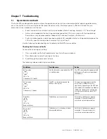
Page 43: ... To check the Event log or Fault log 1 Press any button on the front panel display to activate the menu options 2 Press the button to select Event log or Fault log 3 Scroll through the listed events or faults The following table describes typical conditions Conditions Possible cause Action Battery mode LED is On 1 beep every 10 seconds A utility failure has occurred and the UPS is in battery mode ...

Page 44: ...e UPS transferred to Bypass mode the UPS will return to normal operation when the temperature drops 5 C below the warning level If the condition persists shut down the UPS Clear vents and remove any heat sources Allow the UPS to cool Ensure the airflow around the UPS is not restricted Restart the UPS If the condition continues to persist contact your service representative The UPS does not start T...

Page 45: ...sk or distributor Units damaged in shipment as a result of improper packaging are not covered under warranty A replacement or repair unit will be shipped freight prepaid for all warrantied units IMPORTANT For critical applications immediate replacement may be available Call the Help Desk for the dealer or distributor nearest you 7 7 4 4 C CE E C Co om mp plliia an nc ce e C Co on nt ta ac ct t Eat...

Page 46: ...40 Eaton 9PX Lithium Ion P 164001006 Rev 01 CE Compliance Contact ...

Page 47: ...00W 9PX3000GRT L 3000VA 2400W Table 8 Extended Battery Module List Model Configuration Battery Voltage For Power Module 9PXEBM48RT L Rack Tower 48Vdc 1500VA 9PXEBM72RT L Rack Tower 72Vdc 2000 2200 3000VA Table 9 Weights and Dimensions Model Dimensions D x W x H inch mm Weight lb kg 9PX1500RT L 17 7 x 17 3 x 3 4 450 x 440 x 86 5 35 5 16 2 9PX2000RT L 23 8 x 17 3 x 3 4 605 x 440 x 86 5 50 6 23 0 9PX...

Page 48: ...attery Bypass Voltage Range 20 15 of nominal value default Noise Filtering Input EMC filter Table 11 Electrical Input Connections Model Input Connection Input cable 9PX1500RT L 5 15P 8ft 2 4m 9PX2000RT L 5 20P 8ft 2 4m 9PX3000RT L L5 30P 8ft 2 4m 9PX1500GRT L IEC C14 IEC 10A 6ft 1 8m 9PX2200GRT L IEC C20 16 A inlet L6 20P to C19 jumper provided 6ft 1 8m 9PX3000GRT L Table 12 Electrical Output All ...

Page 49: ...g on page 14 Battery mode 102 130 12s 130 2s Overload warning then transfer to stop output Output Overload Bypass Mode 102 110 Overload warning 110 130 shutdown after 5mins 130 150 shutdown after 15s 150 shutdown after 300ms Percent is based on nominal current in bypass mode Voltage Waveform Sinewave Harmonic Distortion 3 THDV on linear load 5 THDV on non linear load Transfer Time Online Mode 0ms ...

Page 50: ...0 V IEC 61000 4 8 Conducted magnetic field 30 A m for output cable 10m Agency Markings CE cULus NOM Energy Star BSMI Operating Temperatures 0 to 40 C 32 to 104 F in Online mode with linear derating for altitude Note thermal protection switches load to Bypass in case of overheating Storage Temperatures 0 to 40 C 32 to 104 F with batteries 25 to 55 C 13 to 130 F without batteries Transit Temperature...

Page 51: ...dc 2200VA 72Vdc 3000VA 72Vdc 9PXEBM48RT 48Vdc 9PXEBM72RT 72Vdc Type Lithium Iron Phosphate LFP battery module Lithium Ion float service life 8 years 25 C Monitoring Integrated battery management system BMS for temperature regulation and life cycle monitoring EBM Battery Cable Length 350 mm 13 78 in Model Specifications ...

Page 52: ...P 16400100601 P 164001006 01 ...

Reviews: