


Eaton 9PX Lithium-Ion User Guide P-164001006—Rev 02
37
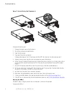
1.
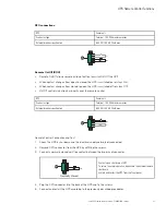
Unplug the EBM power cable and battery detection cable from the UPS. If additional EBM(s) are installed,
unplug the EBM power cable and battery detection cable from each EBM.
2.
Replace the EBM(s). See "Recycling the used equipment" for proper disposal.
A small amount of arcing may occur when connecting an EBM to the UPS. This is normal and will not harm
personnel. Insert the EBM cable into the UPS battery connector quickly and firmly.
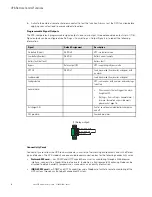
3.
Plug the EBM cable(s) into the battery connector(s). Up to four EBMs may be connected to the UPS.
4.
Verify that the EBM connections are tight and that adequate bend radius and strain relief exist for each
cable.
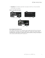
5.
Connect the battery detection cable(s) to the connector of the UPS and of the EBM(s).
6.
Continue to the
7.
If the UPS was shut down during the battery replacement process see
.
66..33
B
Baatttteerryy S
Seettttiinnggss R
Reesseett
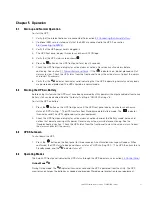
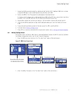
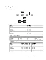
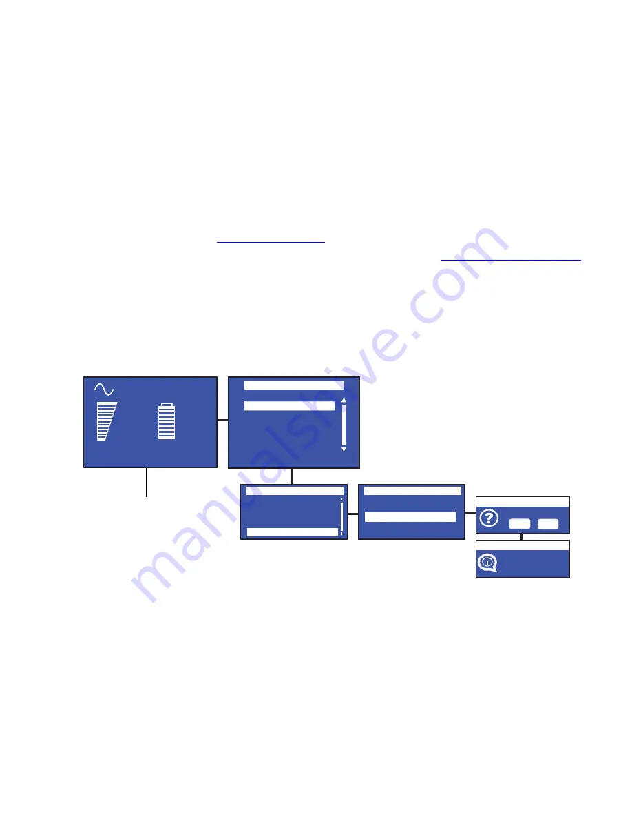
After replacement of the internal UPS batteries and extended battery modules the BMS auto setup and battery
life settings will need to be reset in the “
Control
” menu of the display.
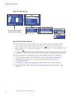
1.
Reset the BMS auto setup function in the “Functions Reset” option of the control menu.
Figure 12. BMS Auto Setup Reset
UPS firmware
Control
Go to bypass
Load segments
UPS firmware
Connectivity test
Functions reset
Measurements
Control
Settings
Event log
Fault log
Identification
Register product
Menu
100 %
100 %
Online mode
Press the Enter Button
to advance the menu
Functions reset
Reset Fault state
Reset power usage
BMS auto setup
Reset battery life
NMC card reset
2.4kW
3.0kVA
19min
1 EBM
Efficiency: 94%
BMS auto setup
Yes
No
Are you sure?
BMS auto setup
Done
2.
Reset the battery life counter in the “Functions Reset” option of the control menu.
Summary of Contents for 9PX2000RT-L
Page 20: ...14 Eaton 9PX Lithium Ion User Guide P 164001006 Rev 02 User Settings ...
Page 36: ...30 Eaton 9PX Lithium Ion User Guide P 164001006 Rev 02 UPS Remote Control Functions ...
Page 46: ...40 Eaton 9PX Lithium Ion User Guide P 164001006 Rev 02 Recycling The Used Equipment ...
Page 50: ...44 Eaton 9PX Lithium Ion User Guide P 164001006 Rev 02 CE Compliance Contact ...
Page 56: ...P 16400100602 P 164001006 02 ...


