4–20kVA Users Guide P-164000669 4–20kVA Users Guide P-164000669—Rev 09
25
CAUTION
EPO and external bypass circuits are safety extra low voltage circuit. This circuit must be isolated from any
hazardous voltage circuits by reinforced insulation.
3.
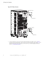
Attach the supplied cable connectors to the ends of the input wires.
4.
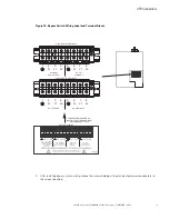
For BPE connections as shown in :
a.
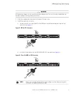
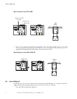
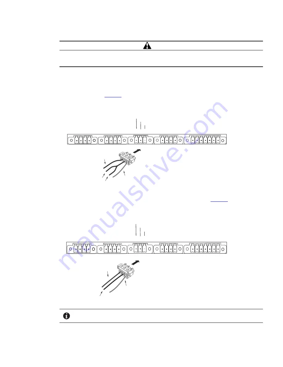
Connect up the 4 wires from the BPE to the 9PXM per the attached drawing and using the 3 pin
connector (see
).
Figure 21. BPE to UPS Connector
3 2 1
4 3 2 1
4 3 2 1
4 3 2 1
7 6 5 4 3 2 1
Force Bypass
Common
On UPS
FORCED
BYPASS IN
(red wire)
BYPASS
NEUTRAL
(black wire)
ON UPS
(white wire)
b.
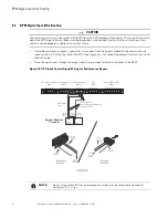
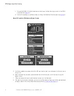
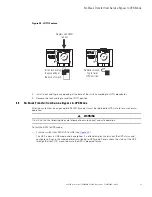
Install the 3 pin connector into the 9PXM UPS BPM CN13 connector (see
).
Figure 22. Three-Pin BPM to UPS Connector
FORCED
BYPASS IN
(red wire)
BYPASS
NEUTRAL
(black wire)
ON UPS
(white wire)
3 2 1
4 3 2 1
4 3 2 1
4 3 2 1
7 6 5 4 3 2 1
Force Bypass
Common
On UPS
NOTE
Make a note to enable Forced and Maintenance Bypass per the following step when
installation is complete and power available.
Summary of Contents for 9PXM
Page 1: ...p n P 164000669 Revision 09 Eaton 9PXM UPS 4 20kVA Users Guide Eaton 9PXM UPS ...
Page 4: ......
Page 8: ...viii 4 20kVA Users Guide P 164000669 4 20kVA Users Guide P 164000669 Rev 09 Table of Contents ...
Page 12: ...xii 4 20kVA Users Guide P 164000669 4 20kVA Users Guide P 164000669 Rev 09 List of Figures ...
Page 14: ...xiv 4 20kVA Users Guide P 164000669 4 20kVA Users Guide P 164000669 Rev 09 List of Tables ...
Page 22: ...8 4 20kVA Users Guide P 164000669 4 20kVA Users Guide P 164000669 Rev 09 Physical Features ...
Page 110: ...96 4 20kVA Users Guide P 164000669 4 20kVA Users Guide P 164000669 Rev 09 Communication Slots ...
Page 130: ...P 16400066909 P 164000669 09 ...

