44
4–20kVA Users Guide P-164000669 4–20kVA Users Guide P-164000669—Rev 09
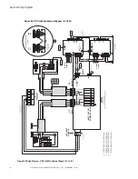
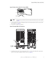
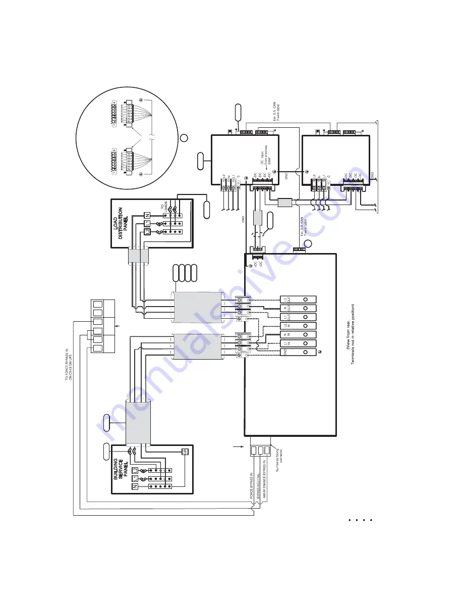
Figure 36. UPS with No External Bypass (L1,L2,N)
Figure 35. Wiring Diagram - UPS with No External Bypass (L1, L2, N)
1
2
3
5
6
3
2
4 6
110/22
0
Input,
110/220
Output
120/208
Input,
120/208
Output
120/240
Input,
120/240
Output
127/220
Input,
127/220
Output
INPUT / OUTPUT POWER BUS BAR
CN13
UP
S
N
O
AU
X
N
O
AU
X
NC
3
2
1
INPUT FROM
FACILITY
EXTERNA
L
DC
AC
OUTPUT
AC
INPUT
UPS
UPS INPUT SIGNALS
CN3
CN4
CN6
CN6
CN4
5
6
AC INPUT TO EBM 1
AC INPUT TO EBM 2
TO NEXT EBM (If installed)
DC INPUT
EBM 1
}
EBM 2
CN3
CN4
CN3
CN4
7
A
A
G
L2
L1
N
G
L2
L1
N
7 6 5 4 3 2 1*
7 6 5 4 3 2 1
UPS CN4
EBM CN4
Supplied Conne
ct
ors
*P
in numbering is right-
to
-le
ft
Input Signal connections
(T
ypical)
8
Summary of Contents for 9PXM
Page 1: ...p n P 164000669 Revision 09 Eaton 9PXM UPS 4 20kVA Users Guide Eaton 9PXM UPS ...
Page 4: ......
Page 8: ...viii 4 20kVA Users Guide P 164000669 4 20kVA Users Guide P 164000669 Rev 09 Table of Contents ...
Page 12: ...xii 4 20kVA Users Guide P 164000669 4 20kVA Users Guide P 164000669 Rev 09 List of Figures ...
Page 14: ...xiv 4 20kVA Users Guide P 164000669 4 20kVA Users Guide P 164000669 Rev 09 List of Tables ...
Page 22: ...8 4 20kVA Users Guide P 164000669 4 20kVA Users Guide P 164000669 Rev 09 Physical Features ...
Page 110: ...96 4 20kVA Users Guide P 164000669 4 20kVA Users Guide P 164000669 Rev 09 Communication Slots ...
Page 130: ...P 16400066909 P 164000669 09 ...

