4–20kVA Users Guide P-164000669 4–20kVA Users Guide P-164000669—Rev 09
1
C
Chhaapptteerr 11 IInnttrroodduuccttiioonn
11..11
IInnttrroodduuccttiioonn
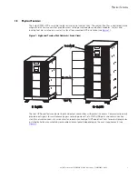
The Eaton® 9PXM uninterruptible power system (UPS) is a modular UPS that contains two battery modules
per slot (two-battery slot) and power control modules (referred to as power modules). These modules plug into
a rack cabinet structure containing additional control, communication and display functions that enable
integrated control of all power modules. The UPS is housed in a single cabinet with either eight or twelve slots
which may be either floor or rack-mounted. Optional extra battery capacity is housed in extended battery
module (EBM) cabinets.
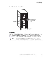
The twelve-slot UPS cabinet can accommodate a maximum of six power modules and two battery modules per
slot in the remaining six slots. However, if a customer chooses to only have one power module they can install
two battery modules per slot in the remaining eleven slots. The eight-slot cabinet can accommodate the same
configuration with two less total units each. Both UPS cabinet models allow their output to be limited such that
an excess number of power modules allow the failure of one or more modules without causing the UPS to lose
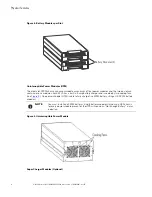
any functionality. Optional super charger modules can be installed in the power module slots.
The power modules can be removed and replaced (easily replaceable) without powering the UPS down if the
UPS has sufficient redundant capacity. Battery modules (2 battery modules per slot) may also be easily
replaced for maintenance. Power control circuitry in the cabinet senses problems in power modules, and
automatically transfers control and load to the remaining power modules. Battery modules and Power modules
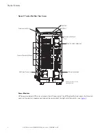
are accessed through removable front panels.
All power modules share the load requirements equally. For example, three power modules are capable of
supplying a total of 12 kVA. If a load requires only 6 kVA, each power module supplies 2 kVA to the output.
If one power module is removed or for some reason fails, each of the two remaining power modules would
supply half of the load, or 3 kVA. In other words, redundancy exists when the load can be supplied by less than
all of the installed power modules.
To permit UPS removal from the power path while maintaining power to the loads, an external bypass switch
is required. This switch is optional but recommended for system serviceability.
11..22
S
Saaffeettyy W
Waarrnniinnggss
IMPORTANT SAFETY INSTRUCTIONS SAVE THESE INSTRUCTIONS
This manual contains important instructions that you should follow during installation and maintenance of the
UPS and batteries. Please read all instructions before operating the equipment and save this manual for future
reference.
•
The 9PXM is a modular UPS with a power range of 4kVA to 20kVA. Each Power Module is rated for up to
4kVA. The 20kVA (N+1) Split-Phase model chassis will have twelve slots, two per row. All of the twelve
slots can accommodate two battery modules per slot. The Power Modules will be restricted to the slots in
only the left side of the chassis, when viewed from the front. A super charger can be installed in any of the
power module slots. This super charger can also be used in an external battery module (EBM). The 16kVA
(12kVA (N+1)) Models will be similar but will have eight slots.
•
Do NOT install more than six power and/or optional super charger modules in the system.
•
Battery modules to be used in the Eaton 9PXM system are model P-103002954. Each battery module
weighs 15 kg (33 lb). Use care in lifting and moving battery modules.
•
All input and output wiring must be copper and adequate to carrying currents as listed in .
•
Torque all bolts holding input and output power conductors to values specified in .
Summary of Contents for 9PXM
Page 1: ...p n P 164000669 Revision 09 Eaton 9PXM UPS 4 20kVA Users Guide Eaton 9PXM UPS ...
Page 4: ......
Page 8: ...viii 4 20kVA Users Guide P 164000669 4 20kVA Users Guide P 164000669 Rev 09 Table of Contents ...
Page 12: ...xii 4 20kVA Users Guide P 164000669 4 20kVA Users Guide P 164000669 Rev 09 List of Figures ...
Page 14: ...xiv 4 20kVA Users Guide P 164000669 4 20kVA Users Guide P 164000669 Rev 09 List of Tables ...
Page 22: ...8 4 20kVA Users Guide P 164000669 4 20kVA Users Guide P 164000669 Rev 09 Physical Features ...
Page 110: ...96 4 20kVA Users Guide P 164000669 4 20kVA Users Guide P 164000669 Rev 09 Communication Slots ...
Page 130: ...P 16400066909 P 164000669 09 ...


