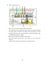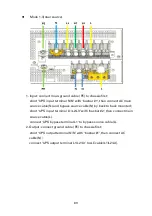
background image

75 

2.


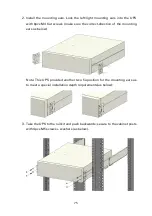
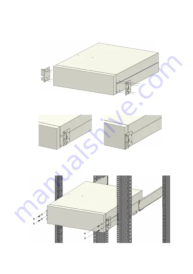
Install  the  mounting  ears.  Lock  the  left/right  mounting  ears  into  the  UPS 

with  8pcs  M4 flat  screws (make  sure  the correct-direction of  the  mounting 

ears as below) 


Note: This UPS provided another two fix-position for the mounting ears as 

to meet a special installation depth requirements(as below): 


3.


Take the UPS to the rail kit and push backwards; secure to the cabinet posts 

with 4pcs M5  washers (as below). 


Summary of Contents for 9SX Series

Page 1: ...Eaton 9SX 15 20KPM CH UPS...

Page 2: ......

Page 3: ...2019 EATON...

Page 4: ...1 2 3 4 5 UPS 6 7 1 2 UPS UPS 3 4 EMC UPS 10 1 UPS 2 3 4 A B C D E 5...

Page 5: ...6 7 1 A 0 50 0 95 B C 2 UPS 25 60 UPS 0 2...

Page 6: ...1 1 2 3 2 1 UPS 3 2 2 EBM 4 2 3 MBP 5 3 8 3 1 8 3 2 10 3 3 12 4 16 4 1 17 4 2 EBM 26 4 3 MBP 28 5 29 5 1 29 5 2 30 6 35 7 37 7 1 37 7 2 38 7 3 41 7 4 UPS 46 8 50 9 51 10 52 54 54 56...

Page 7: ...1 1 Eaton 9SX 15 20KPMCH UPS UPS UPS UPS UPS 1 0 32 40 1 13A LCD 96 95 Eaton 9SX 15 20KPMCH UPS W H D mm kg 9SX 15KPMCH 438 129 3U 559 24 8 9SX 20KPMCH 438 129 3U 559 24 8 1 2 D 559mm...

Page 8: ...U 438 129 3U 559 51 8 103 6 2 16 9Ah 9SX EBM480RT6U 438 129 3U 559 60 5 121 2 20 9Ah 1 2 2 D 559mm MBP W H D mm kg MBP20K 438 129 3U 465 12 8 MBP MBP20KPDU 438 129 3U 465 13 6 MBP MBP20KPARA 438 129 3...

Page 9: ...3 2 2 1 UPS 1 2 LCD 2 1 2 2 2 3 LED 1 2 3 EPO 4 RJ45 5 USB 6 RS232 7 RJ45 Modbus BMS 8 9 10 11 AC...

Page 10: ...4 2 2 EBM 1 2 1 3 2 4 RJ45 5...

Page 11: ...5 2 3 MBP MBP 1 2 logo MBP...

Page 12: ...6 1 RJ45 2 AC 3 AC 4 UPS 5 6 MBP 1 RJ45 2 AC 3 AC 4 AC 5 UPS 6 IEC 7 IEC 8 9 10...

Page 13: ...7 1 1 MBP 1 RJ45 2 AC 3 AC 4 AC 5 UPS1 6 UPS2 7 8...

Page 14: ...8 3 3 1 3 1 1 UPS EBM MBP...

Page 15: ...9 3 1 2 UPS UPS 9SX 15KPMCH 9SX 20KPMCH USB RS232 O O O O O O O EBM 9SXEBM384RT6U 9SX EBM480RT6U O O O MBP...

Page 16: ...5KPM CH 6 6 16 16 16 16 16 16 10 10 6 6 6 6 6 6 6 6 10 10 35 35 16 16 35 16 16 16 10 10 35 35 6 6 35 6 6 6 10 10 9SX 20KPM CH 10 10 25 25 25 25 25 25 10 10 10 10 10 10 10 10 10 10 10 10 50 50 25 25 50...

Page 17: ...H D 125A 125A D 63A 63A D 100A 100A D 40A 40A 9SX 20KPMCH D 160A 160A D 63A 63A D 125A 125A D 63A 63A 9SX 15KPMCH 100A 40A 9SX 20KPMCH 125A 63A mm 6 DRNB6 6 10 DRNB6 10 16 DRNB8 16 25 DRNB8 25 35 DRNB...

Page 18: ...12 3 3 1 2 500mm 3 3 3 1 UPS 19 800mm 1 2U M5 D 415 763mm 8 M5...

Page 19: ...13 2 8 M4 UPS 3 UPS UPS 4 M5...

Page 20: ...14 LCD LCD UPS 3 3 2 EBM EBM UPS 1 EBM UPS 2 EBM 2 3U 6U 3 EBM...

Page 21: ...15 1 EBM UPS UPS 2 UPS UPS EBM 1 EBM UPS 2 EBM 2 UPS 3 EBM 3 3 3 MBP MBP UPS...

Page 22: ...16 4 UPS EBM UPS UPS UPS UPS UPS...

Page 23: ...17 4 1 4 1 1 UPS 1 UPS PE N N L1 L2 L3 2 UPS L1 L2 L3 3 UPS PE N N L1 L2 L3 4 PE N N UPS...

Page 24: ...18 UPS 8 1 2 2 2 NA 3 1 PE 1 UPS N N 2 L2 L3 UPS L1 L2 L3 2 L1 L2 L3 L1 2 PE 1 UPS N N 2 UPS L1 L2 L3 L...

Page 25: ...19 1 PE 1 UPS N N N L1 L2 L3 UPS L1 L2 L3 2 L1 L2 L3 L 2 PE 1 UPS N N 2 UPS L1 L2 L3 L...

Page 26: ...20 1 PE 1 UPS N N L1 L2 L3 UPS L1 L2 L3 L1 L2 L3 2 PE 1 UPS N N L1 L2 L3 UPS L1 L2 L3...

Page 27: ...21 1 PE 1 UPS N N N L1 L2 L3 UPS L1 L2 L3 L1 L2 L3 L1 L2 L3 2 PE 1 UPS N N L1 L2 L3 UPS L1 L2 L3...

Page 28: ...22 1 PE 1 UPS N N 2 UPS L1 L2 L3 2 L1 L2 L3 L 2 PE 1 UPS N N 2 UPS L1 L2 L3 L...

Page 29: ...23 1 PE 1 UPS N N N 2 L1 L2 L3 L 2 L1 L2 L3 L 2 PE 1 UPS N N 2 UPS L1 L2 L3 L...

Page 30: ...24 1 PE 1 UPS N N 2 2 UPS L1 L2 L3 L L1 2 PE 1 UPS N N L1 L2 L3 UPS L1 L2 L3...

Page 31: ...25 1 PE 1 UPS N N N 2 UPS L1 L2 L3 L L L1 2 PE 1 UPS N N L1 L2 L3 UPS L1 L2 L3...

Page 32: ...26 4 2 EBM EBM UPS 1 UPS EBM 2 EBM UPS 3 EBM UPS LCD 4 EBM EBM EBM EBM UPS EBM UPS 32 EBM 1 EBM 2 16 UPS 6 EBM EBM 2 UPS...

Page 33: ...27 EBM RJ45 1 EBM 1 EBM UPS 2 EBM UPS EBM 3 2 1 EBM 2 EBM 3 EBM...

Page 34: ...28 4 3 MBP MBP UPS MBP UPS...

Page 35: ...29 5 1 UPS 2 UPS 1 1 MBP UPS UPS 10 UPS 20 UPS 20 UPS 5 5 1 UPS UPS 3 1 1 MBP...

Page 36: ...50 50 50 25 25 16 16 10 10 16 10 10 10 25 25 95 95 50 50 95 50 50 50 25 25 95 95 10 10 95 10 10 10 25 25 3 35 35 95 95 95 95 95 95 50 50 35 35 16 16 35 16 16 16 50 50 185 185 95 95 185 95 95 95 50 50...

Page 37: ...25 25 16 16 25 16 16 16 35 35 120 120 70 70 120 70 70 70 35 35 120 120 16 16 120 16 16 16 35 35 3 50 50 150 150 150 150 150 150 70 70 50 50 25 25 50 25 25 25 70 70 240 240 150 150 240 150 150 150 70 7...

Page 38: ...32 5 2 1 UPS 25pin UPS 1 2...

Page 39: ...33 5 2 2 1 UPS EBM 2 UPS EBM 4 2 3 UPS 5 2 1...

Page 40: ...34 5 2 3 1 2 UPS 5 2 1 5 2 4 1 1 MBP MBP UPS 1 1 MBP UPS MBP...

Page 41: ...35 6 UPS USB RS232 RS 232 2400 8 1 0 2400 8 1 USB RS232 USB EPO EPO UPS EPO UPS UPS EPO UPS...

Page 42: ...36 Dry in Dry out Dry in Dry out UPS 7 3 4 Modbus BMS Modbus BMS Modbus BMS Modbus 5 UPS SW 2 Off ON BMS SW 1 Off ON Genepi IT Genepi FA Modbus Relay MS...

Page 43: ...37 7 7 1 LED UPS UPS UPS UPS UPS UPS UPS UPS UPS UPS 2 UPS 10 UPS 1 UPS UPS...

Page 44: ...38 7 2 Eaton 9SX 15 20KPMCH 4 3 65K 7 2 1...

Page 45: ...39 7 2 2 UPS UPS...

Page 46: ...40 7 2 3 UPS UPS UPS UPS1 UPS...

Page 47: ...41 7 2 4 5 LCD LCD LCD 15 LCD 7 3 7 3 1 UPS...

Page 48: ...42 UPS UPS 7 3 2 UPS 100...

Page 49: ...43 7 3 3 UPS 5 3 LCD 5 UPS 6 4 UPS UPS UPS UPS UPS UPS UPS 7 3 4 UPS 5 3 LCD 5...

Page 50: ...44 UPS English YYYY MM DD HH MM SS 0 100 xxx V 110V xxx V 276V 5 10 xxx V 110V xxx V 276V 5 10 220V 230V 240V 50Hz 60Hz ESS 50 105 0 100 0 999 0 100 1A 13A AH...

Page 51: ...16 9AH 9 2 2 2 2 16 9AH 18 4 3 3 2 16 9AH 27 6 4 4 2 16 9AH 36 8 5 5 2 16 9AH 45 10 6 6 2 16 9AH 54 12 1 2 Ah LCD 18 2 16 18 4 26 2 16 26 6 38 2 16 38 8 65 2 16 65 13 100 2 16 100 13 120 2 16 120 13...

Page 52: ...46 7 4 UPS 7 4 1 UPS UPS UPS UPS UPS UPS 4 1 UPS LCD EATON UPS UPS 1 EPO 2 LCD 3 LCD UPS 4 UPS 5 UPS EPO 1 UPS UPS...

Page 53: ...47 UPS UPS UPS UPS LCD UPS 10 7 3 4 0 1 UPS LCD 10 LCD UPS 1 UPS UPS UPS UPS 4 7 3 4 LCD 7 4 2 UPS UPS 3s LCD UPS UPS UPS 3s LCD UPS UPS UPS...

Page 54: ...48 7 4 3 UPS 0ms 10ms ESS 2ms 0ms 50Hz 60Hz UPS UPS 0 UPS 200ms UPS 200ms UPS 10 10 UPS 10 UPS 105 UPS UPS 10 5 9 6 UPS EBM AH UPS 60 UPS...

Page 55: ...49 7 4 4 UPS 1 2 UPS 1 UPS UPS UPS UPS UPS 1 UPS UPS UPS 3 UPS LCD 7 4 2 UPS 3s UPS 7 4 5 UPS 2 UPS 18AH 3 UPS 27AH UPS...

Page 56: ...50 8 UPS 1 UPS UPS 2 15 25 3 UPS 3 4 4 6 2 1 5 14 6 7 3 5...

Page 57: ...51 9 UPS UPS 24 365 400 889 3938...

Page 58: ...52 10 UPS 1 2 3 107 120 63F 642 641 644 646 648 645 UPS 647 UPS 640 643 300 Bus BUS 301 Bus BUS 302 Bus BUS 303 Bus BUS 304 Bus BUS 308 Bus BUS...

Page 59: ...53 100 Bus Bus 805 UPS 822 L1 823 L2 824 L3 70D 70C 704 705 808 208 70E 010 UPS 017 806 EPO 706 203 501 004 UPS 50 UPS 007 20E 80D 811 00E 00F...

Page 60: ...54...

Page 61: ...kW 50 60Hz 100 300VAC 220 230 240VAC 35A 105A 43A 129A 40 70Hz 1 13A 2A 220 230 240VAC 105 125 10 125 150 30 150 0 5 0ms 0ms 2 192 2 240VDC 2 192VDC 2 16 2 20 2 16 0 50 40 50 0 95 4000m 1km 15 40 25 6...

Page 62: ...56...

Page 63: ...Eaton 9SX 15 20KPM AU Series Online UPS Eaton DXRT15 20KS IN Series Online UPS...

Page 64: ...Copyright 2019 EATON All rights reserved...

Page 65: ...ted with the risk of electric shock symbol Important instructions that must always be followed Do not discard the UPS or the UPS batteries in the trash This product contains sealed lead acid batteries...

Page 66: ...ger electrical shock burns The short circuit current may be very high Precautions must be taken for all handling Wear rubber gloves and boots Do not lay tools or metal parts on top of batteries Discon...

Page 67: ...y Special precautions The unit is heavy wear safety shoes and use vacuum lifter preferentially for handling operations All handling operations will require at least two people unpacking lifting instal...

Page 68: ...ection 72 3 3 Mechanical installation 74 4 Wiring for AC Cable 78 4 1 Input Output wiring 79 4 2 Wiring with external battery modular EBM 90 4 3 Wiring with single MBP 92 5 Parallel UPS install 93 5 1...

Page 69: ...iendly interface More convenient operation online double conversion mode efficiency is up to 96 battery mode efficiency is up to 95 more environmentally friendly and energy efficient We recommend that...

Page 70: ...ulations concerning batteries The battery may be removed to comply with regulations and in view of correct disposal 1 2 Electronic equipment protection The uninterruptible power system UPS protects yo...

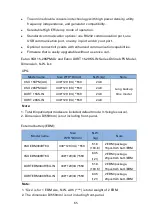
Page 71: ...15KPM AU 438 129 3U 559 24 8 Long backup time model 9SX 20KPM AU 438 129 3U 559 24 8 DXRT 15KS IN 438 129 3U 559 24 8 DXRT 20KS IN 438 129 3U 559 24 8 Note 1 Total 8 input output modes are included d...

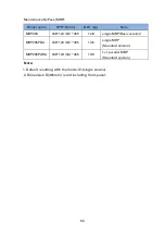
Page 72: ...29 3U 465 12 8 single MBP Basic version MBP20KPDU 438 129 3U 465 13 6 single MBP Standard version MBP20KPARA 438 129 3U 465 19 9 1 1 parallel MBP Standard version Note 1 Default is setting with the mo...

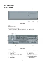
Page 73: ...uding 2 1 Power button 2 2 Touch screen 2 3 LED indicator Rear view Note 1 Parallel port 2 Dry in out port 3 EPO port 4 RJ45 port Detect EBM MBP 5 USB port 6 RS232 port 7 RJ45 port Modbus BMS 8 DIP sw...

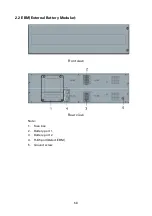
Page 74: ...68 2 2 EBM External Battery Modular Front view Rear view Note 1 Fuse box 2 Battery port 1 3 Battery port 2 4 RJ45 port Detect EBM 5 Ground screw...

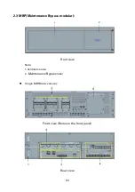
Page 75: ...69 2 3 MBP Maintenance Bypass modular Front view Note 1 Ventilation area 2 Maintenance Bypass label Single MBP basic version Front view Remove the front panel Rear view...

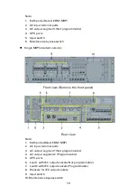
Page 76: ...rd version Front view Remove the front panel Rear view Note 1 RJ45 ports Detect EBM MBP 2 AC input terminal ports 3 AC output segment 1 Not programmable 4 AC output segment 2 Programmable 5 UPS ports...

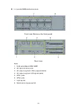
Page 77: ...t view Remove the front panel Rear view Note 1 RJ45 ports Detect EBM MBP 2 AC input terminal ports 3 AC output segment 1 Not programmable 4 AC output segment 2 Programmable 5 UPS1 ports 6 UPS2 ports 7...

Page 78: ...collision or damage during transportation If any damage is found or the accessories is missing please contact your carrier or dealer immediately Forbidden to carry the front rear panel of the module 3...

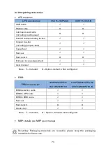
Page 79: ...ack rail kit O O End user License Agreement User manual Note Included O Option default is Not configured EBM EBM accessories 9SXEBM384RT6U 9SX EBM480RT6U DXRTEBM384RT6U IN DXRTEBM480RT6U IN EBM detect...

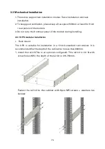
Page 80: ...front rear panel of the module during installing 3 3 1 UPS modular installation Rack mount The UPS is suitable for installation in a 19 inch standard rack cabinet It is recommended that the depth of...

Page 81: ...e sure the correct direction of the mounting ears as below Note This UPS provided another two fix position for the mounting ears as to meet a special installation depth requirements as below 3 Take th...

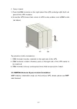
Page 82: ...cally adjust the display direction 3 3 2 EBM modular installation Rack mount EBM modular installation steps are the same as UPS Pay attention to this installation 1 EBM modular must be installed on th...

Page 83: ...s below Pay attention to this installation 1 EBM modular must be installed on the right side of the UPS 2 EBM modular contains 2 battery pack so the right side of the UPS needs to be reserved 3 EBM mo...

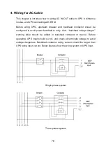
Page 84: ...onfigured to avoid power backfeed to unity And backfeed voltage danger warning lable should be added in backfeed contactor or device Before operating UPS input should cut off and check all terminals v...

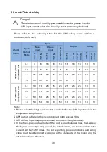
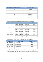
Page 85: ...ing protection device and wiring cable must be determined according to the standards of the region and the actual situation of the user Model name Input Output Mode Input Output Battery Main input Byp...

Page 86: ...0A 3 phase main input D type 63A 63A 1 phase bypass input D type 125A 125A 3 phase bypass input D type 63A 63A Recommended output circuit breaker current specifications Model name Output mode Breaker...

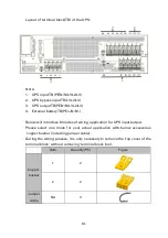
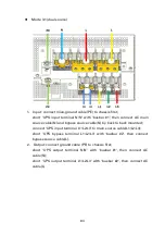
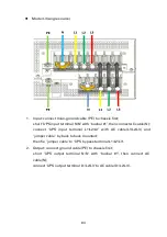
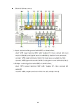
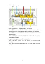
Page 87: ...will introduce 8 modes of wiring application for UPS input output Please select one mode for your actual application with below accessories copper busbar including jumper cable During the wiring proc...

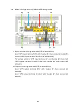
Page 88: ...ect UPS input terminal L2 L3 to AC cable L2 L3 Fix jumper cable to UPS input terminal L1 and busbar 2 then short UPS bypass terminal L1 L2 L3 with this busbar 2 and connect AC cable L1 2 Output connec...

Page 89: ...cable N by back to back mounted connect UPS input terminal L1 L2 L3 to main source cable L1 L2 L3 short UPS bypass terminal L1 L2 L3 with busbar 2 then connect bypass source cable L 2 Output connect...

Page 90: ...cable N connect UPS input terminal L1 L2 L3 with AC cable L1 L2 L3 and jumper cable by back to back mounted then fix jumper cable to UPS bypass terminal L1 L2 L3 2 Output connect ground cable PE to c...

Page 91: ...d bypass source cable N by back to back mounted connect UPS input terminal L1 L2 L3 to main source cable L1 L2 L3 connect UPS bypass terminal L1 L2 L3 to bypass source cable L1 L2 L3 2 Output connect...

Page 92: ...able N Fix jumper cable to UPS input terminal L1 L2 L3 and busbar 2 then short UPS bypass terminal L1 L2 L3 with this busbar 2 and connect AC cable L 2 Output connect ground cable PE to chassis first...

Page 93: ...N by back to back mounted short UPS input terminal L1 L2 L3 with busbar 2 then connect main source cable L short UPS bypass terminal L1 L2 L3 with busbar 2 then connect bypass source cable L 2 Output...

Page 94: ...Fix jumper cable to busbar 2 then short UPS input terminal L1 L2 L3 with this busbar 2 and connect AC cable L connect this jumper cable to UPS bypass terminal L1 finally 2 Output connect ground cable...

Page 95: ...bypass source cable N by back to back mounted short UPS input terminal L1 L2 L3 with busbar 2 then connect main source cable L connect UPS bypass terminal L1 to bypass source cable L 2 Output connect...

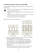
Page 96: ...g 4 Do not reverse the polarity of the external battery EBM wiring schematic diagram is shown below Sigle string EBM Multiple strings EBM Battery cable installation sequence connect UPS first then con...

Page 97: ...S EBM to EBM cable 2 Connecting EBM to EBM The schematic diagram the EBM to USP wiring Note If the UPS wired with other type EBM User s own EBM please follow wiring diagram as above and chapter 4 1 ta...

Page 98: ...ional modular UPS can be used with the MBP to implement the maintenance bypass switching function to ensure that the output of the system is not affected during the UPS maintenance see the User Manual...

Page 99: ...or the parallel system Caution Wiring length requirement When the distance between the load and the parallel UPS is less than 10 meters the length difference between the input output lines between the...

Page 100: ...r a better cable connection as shown below Rack mount for parallel system Tower mount for parallel system 5 2 wiring Cable select table for the parallel system AC IN and AC OUT Parallel system install...

Page 101: ...70 35 35 1 3 120 120 16 16 120 16 16 16 35 35 3 UPS 3 1 50 50 150 150 150 150 150 150 70 70 3 3 50 50 25 25 50 25 25 25 70 70 1 1 240 240 150 150 240 150 150 150 70 70 1 3 240 240 25 25 240 25 25 25 7...

Page 102: ...by one with parallel cable 25pin as accessory to be a close loop as shown below To reduce the risk of parallel system damage 1 Please use the configured parallel cable which is accessoried in UPS 2 Af...

Page 103: ...ent battery 1 In the parallel system if each UPS is configured with the EBM of this series please refer to the following illustration for installation and placement 2 Please refer to chapter 4 2 for t...

Page 104: ...lease refer to the following figure 5 2 4 Wiring with the 1 1 Parallel MBP MBP is UPS s optional modular parallel system can be used with MBP to implement the maintenance bypass switching function to...

Page 105: ...f USB and RS232 are connected at the same time USB communication priority EPO Emergency Power Off EPO on the rear panel of UPS disconnecting the EPO can cut off the output of the UPS Need to resume UP...

Page 106: ...tion with a maximum of 5 UPS When connecting hand in hand you need to use one two terminal please contact the service person for the terminal SW 2 in the DIP switch is the enable terminal resistance s...

Page 107: ...ncy mode Light off UPS no output at present Power on initialization Shutdown Bypass no output Power button Function Description Power on Turn off Clear fault Press to turn the UPS on When UPS is worki...

Page 108: ...0KPMAU Series and Eaton DXRT 15 20KS IN Series are equipped with 4 3 inch 65K true color touch screen graphical menu touch operation convenient and efficient to use 7 2 1 User Interface overview Start...

Page 109: ...ad on the right side of the screen after the cursor appears The confirm password is same as the setting password Be sure to keep the password If you need to control the Menu and the Setting you need t...

Page 110: ...arm message Input information There are three input status displays for bypass mains and battery Highlighted color represents the current input state System status Color distinguishes system status bl...

Page 111: ...en there is no operation within 5 minutes the LCD will enter the screen saver mode In this mode touch the screen to re light the LCD and the LCD will return to the previous page Under any page when th...

Page 112: ...f all UPS in the parallel system on one UPS 6 3 2 Query or clear UPS history Click the history icon on the menu page to enter the history page The event or alarm list can be distinguished according to...

Page 113: ...performed again during this period If you want to cancel the password protection please cancel the password protection in Setting Password In the Parallel system there 6 kinds of control operations t...

Page 114: ...witch back to the main page Control and setting will be locked for 5 minutes and will not be able to operate again during this time If you want to cancel the password protection please cancel the pass...

Page 115: ...led Disable Low Battery Warning 0 100 Low RemindTime Warning 0 999min Restart Battery Level 0 100 Charge Current 1A 13A Extearnal Battery Module Auto Detection External Battery Setting EBM External Ba...

Page 116: ...EBM 4 2 16 PCS 9AH 36AH 8A 5 Str EBM 5 2 16 PCS 9AH 45AH 10A 6 Str EBM 6 2 16 PCS 9AH 54AH 12A 1 Str 2 EBMs Self configured battery charge current setting table Battery Unit AH Battery number Total A...

Page 117: ...the utility power The fan starts to rotate the LCD displays EATON Startup animation then enters the main page UPS default Bypass enable the main page shows UPS working in bypass mode The default inpu...

Page 118: ...Startup the UPS on Battery Without utility power When the UPS is connected to the battery wait at least 10 seconds before pressing the power button The battery can be turned on or disabled For detail...

Page 119: ...ttery mode Press the button for more than 3s the LCD pops up to confirm the shutdown page After clicking Confirm the UPS performs shutdown The UPS output is interrupted and goes into standby mode Afte...

Page 120: ...r exceeding 105 of the rated power However when there is special requirements the value can be reset When the actual load of the UPS exceeds the set value the UPS can send warning To remind the user t...

Page 121: ...em has been turned on to the inverter state press the button to establish the working power to the other UPS and the newly powered UPS will automatically trun to the inverter state 3 Parallel UPS Shut...

Page 122: ...Battery ambient temperature should be maintained between 15 25 C 3 If battery is not used for a long time it is recommended to charge it every 3 months 4 In normal use the battery is charged and disch...

Page 123: ...the battery is damaged Replace it immediately by professional person 644 Negative battery low voltage 646 Positive battery overcharge Battery voltage high Check the battery and charger If the battery...

Page 124: ...pplier 010 Main SPS fault UPS internal power supply is abnormal Please contact your supplier 017 Auxiliary SPS fault 806 Emergency shutdown Shut down in emergency Please check EPO terminal status 706...

Page 125: ...harging current 1 13A adjustable default 2A Output Rated voltage Phase voltage 220 230 240VAC Overload 105 125 Load 10 minutes transfer to Bypass 125 150 Load 30 seconds transfer to Bypass 150 Load 0...

Page 126: ...120 Storage temperature without battery 25 60 Criterion Safety EN62040 1 2008 A1 2013 EMC EN 62040 2...

Page 127: ......

Page 128: ...121 614 40045 00...

Reviews: