background image

Installation

Eaton Advanced ePDU User’s Guide P-164000042—Rev 1

www.eaton.com/ePDU

17

4.

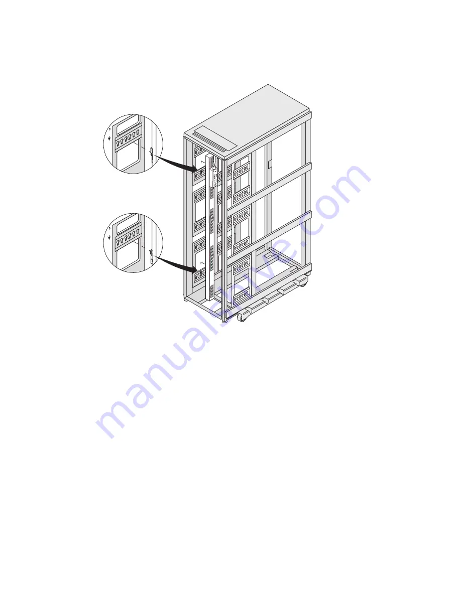
Insert the top and bottom mounting buttons into the appropriate keyhole slots, as shown in Figure 13.

Figure 13. Securing the ePDU

5.

Push down to secure the ePDU in position.

Summary of Contents for Advanced Enclosure Power Distribution Unit (ePDU)

Page 1: ...Eaton Advanced Enclosure Power Distribution Unit ePDU User s Guide...

Page 2: ...emarks of Microsoft Corporation in the United States and other countries Mozilla and Firefox are registered trademarks of the Mozilla Foundation National Electrical Code and NEC are registered tradema...

Page 3: ...nications Operation of this equipment in a residential area is likely to cause harmful interference in which case the user will be required to correct the interference at his own expense ICES 003 This...

Page 4: ...ith the risk of electric shock symbol CAUTION REFER TO OPERATOR S MANUAL Refer to your operator s manual for additional information such as important operating and maintenance instructions This symbol...

Page 5: ...age Nuts with Mounting Clip Feet 14 Using Keyholes with Mounting Buttons 16 Using Keyholes with Mounting Buttons and Clip Feet 18 Grounding the ePDU 19 Hardware Connectivity 20 Connecting to a Compute...

Page 6: ...d Event Log 46 Download the Eaton MIB Files 46 Actions on Individual Outlets and Groups of Outlets 47 Restart the Network Management Card 47 Restore the Default Factory Settings of the Network Managem...

Page 7: ...78 Configure Multi Users 79 Configure the DNS 79 Enable Disable SSL Encryption 79 Enable Disable the Telnet Interface 80 8 SERIAL INTERFACE OPERATION 81 SNMP Agent 81 Enable disable the SNMP Agent 82...

Page 8: ...7 Serial Interface 98 DIP Switch Configuration 99 Upload New Firmware Files 99 Restart the Network Management Card 103 Troubleshooting 103 Acknowledging the Alarm 103 Types of Alarms 104 Alarms Notice...

Page 9: ...MA with control and monitoring at the outlet level These capabilities are expressed in the model numbers of the ePDUs Eaton ePDU Models There are 28 Eaton Advanced ePDU models These models are categor...

Page 10: ...Power Cord eSWA03 Switched Model Shown Figure 3 shows an example of the Type 3 ePDU Figure 3 Type 3 Three Phase Model eSWA05 Switched Model Shown eSWA03 EU C19 C20 eAMA07 EU IEC 60309 16A C19 eAMA08 E...

Page 11: ...DU 3 Figure 4 shows an example of the Type 4 ePDU Figure 4 Type 4 Single Phase Model eMAA13 Managed Model Shown Figure 5 shows an example of the Type 5 ePDU Figure 5 Type 5 Single Phase Model eAM001 A...

Page 12: ...com ePDU 4 Figure 6 shows an example of the Type 6 ePDU Figure 6 Type 6 Three Phase Model eMA007 Managed Model Shown Figure 7 shows an example of the Type 7 ePDU Figure 7 Type 7 Three Phase Model eMA...

Page 13: ...ment protecting your critical equipment The EMP measures temperatures between 0 C and 80 C 32 F and 176 F with an accuracy of 1 C The EMP measures relative humidity between 10 and 90 with an accuracy...

Page 14: ...SNMP or a console emulator such as HyperTerminal l Compatibility with network management tools such as Intelligent Power Manager IPM facilitated by SNMP protocol Power Control Management l Control of...

Page 15: ...ed ePDU User s Guide P 164000042 Rev 1 www eaton com ePDU 7 Configurability and Security l Configurable alarm thresholds l Configurable user security control l Address specific IP security mask to pre...

Page 16: ...grounded outlets at both the computer and monitor When using a backup UPS power the computer monitor and appliance off the supply l The installation power outlet used for the power supply to this equ...

Page 17: ...ical outlets l Verify that the power outlet is near the equipment and is easily accessible so that the ePDU can be disconnected quickly l Do not overload the power outlet when you install multiple dev...

Page 18: ...kage Contents Table 1 lists the parts that are included with Advanced ePDU models Table 2 on page 12 lists the detachable ePDU power cords included with some Advanced ePDU models See Table 29 on page...

Page 19: ...1 2 Anti sliding safety screw 2 Cage nut 2 Screw for mounting clip feet and cage nut assembly 2 Screw for keyhole mounting button 2 Hex nut for keyhole mounting button 2 Keyhole mounting button Table...

Page 20: ...king block that stabilizes the ePDU during transport The Ethernet cable is intended for customers with small data centers for maintenace or for checks in a warehouse setting Larger data center custome...

Page 21: ...s 2 Using the screws and a Phillips screwdriver attach the brackets in a configuration appropriate for your ePDU model and your installation needs See the examples shown in Figure 9 DANGER Electrical...

Page 22: ...upplied Position and lock the two cage nuts far enough apart to stabilize the top and bottom of the ePDU when mounted on the rail Attach the cage nuts with a flat blade screwdriver 2 Locate the two mo...

Page 23: ...e ePDU and tighten the screw firmly 4 Snap the ePDU into the mounting clip feet When you hear a clicking sound for each mounting clip foot the ePDU is secure 5 Carefully move the ePDU into position ag...

Page 24: ...2 Using the supplied screws and a Phillips screwdriver install the mounting buttons on the ePDU far enough apart to stabilize the ePDU when mounted on the rail See Figure 12 Figure 12 Installing the...

Page 25: ...PDU User s Guide P 164000042 Rev 1 www eaton com ePDU 17 4 Insert the top and bottom mounting buttons into the appropriate keyhole slots as shown in Figure 13 Figure 13 Securing the ePDU 5 Push down t...

Page 26: ...d Clip Feet To install the ePDU with mounting buttons installed on the mounting clip feet 1 Locate the two mounting clip feet mounting buttons screws and hex nuts supplied Using a Phillips screwdriver...

Page 27: ...e ePDU and tighten the screw firmly 4 Carefully move the ePDU into position against the rail verifying that the anti sliding safety screw is above the topmost mounting clip see Figure 14 on page 18 5...

Page 28: ...e ePDU to a computer 1 Verify that the computer has a communication program such as HyperTerminal or PuTTY IMPORTANT You must use the supplied DB9 to RJ 45 cable PN 720 B1817 00 Do not use a substitut...

Page 29: ...bits 1 Parity None Flow control None 6 Verify that the ePDU is turned on 7 Press Enter to display the opening configuration prompt and type admin the access password NOTE If your computer does not ha...

Page 30: ...tain an Ethernet cable 2 Connect one end of the cable to the Ethernet connector on the ePDU Connect the other end of the cable to the Ethernet connector on the router or other LAN device See Figure 17...

Page 31: ...on the EMP then connect the other end of the cable to the RS 232 connector on the ePDU See Figure 19 Figure 19 Connecting the EMP NOTE You can install an optional EMP now or after completing the ePDU...

Page 32: ...d displays the Eaton startup screen while starting After five seconds the sequence of screensaver screens for this ePDU model begin cycling 5 Verify that no alarms display on the LCD To resolve alarms...

Page 33: ...et 1 Outlet 2 Outlet 3 Model Serial Number Use Outlet 4 Outlet 5 Outlet 6 Model Serial Number Use Outlet 7 Outlet 8 Outlet 9 Model Serial Number Use Outlet 10 Outlet 11 Outlet 12 Model Serial Number U...

Page 34: ...Management Card in Operation Mode This procedure describes how to set the Network Management Card in Operation mode and enable the card before configuring IP settings To enable the Network Management...

Page 35: ...ddress subnet mask gateway address and Domain Name System DNS servers This requires a short retrieval process 2 The IPv4 address can be configured using a more detailed manual process 3 The default IP...

Page 36: ...system to build the new configuration settings and make those settings permanent If you activate a hardware restart before the 15 seconds have elapsed all new configuration settings are lost See Rest...

Page 37: ...Settings and press Enter see Figure 22 Figure 22 Eaton ePDU Configuration Utility 7 Type 2 Network Settings and press Enter 8 Type 3 Communication Control and press Enter see Figure 23 Figure 23 Netw...

Page 38: ...ask and press Enter Type the subnet mask and press Enter Figure 25 IPv4 Configuration Menu 18 Type 0 Return to previous menu and press Enter 19 Type 0 Return to previous menu and press Enter 20 Type 0...

Page 39: ...dynamic IPv4 address configuration To manually enter the default address 1 Access a Web browser 2 Type the default address in the address bar http 192 168 123 123 The Web interface opens with the ePD...

Page 40: ...ddresses 8 Type 1 Network Management Card Settings and press Enter 9 Type 2 Network Settings and press Enter 10 Type 2 IPv6 Configuration and press Enter 11 The IPv6 settings are displayed Networks Th...

Page 41: ...the Echo typed characters locally option 4 Press Enter The Login menu displays 5 Type admin The Eaton ePDU Configuration Utility menu displays 6 Type 1 Network Management Card Settings and press Enter...

Page 42: ...gement Card Operation To determine if the Network Management Card is operational after IPv4 or IPv6 network configuration is completed 1 Access a Web browser 2 Type the IPv4 or IPv6 address in the add...

Page 43: ...r 5 Operation Overview This chapter introduces the operation features of the Eaton Advanced Enclosure Power Distribution Unit ePDU Figure 27 shows an isolated view of the display and connectivity area...

Page 44: ...to upgrade or read only operation The default setting is normal operation For more information see Operation Mode DIP Switches on page 42 4 Reset opening Restarts the ePDU Network Management Card Res...

Page 45: ...tings that specify the degree of environmental protection for electrical equipment The IEC60309 input connector plugs that are either splash resistant S or waterproof W l Splash resistant plugs are IP...

Page 46: ...color coded for easy identification on the ePDU as shown in Figure 29 Figure 29 Outlet Groups LEDs and Group Circuit Breakers eMA007 Model Shown Table 6 defines the outlet groups for each model Group...

Page 47: ...eMAA13 A1 to A12 B1 to B12 eMAA14 A1 to A8 B1 to B8 C1 to C8 eAM001 A1 to A12 B1 to B12 eAM002 A1 to A8 B1 to B8 C1 to C8 eAM003 A1 to A8 B1 to B8 C1 to C8 eAM004 A1 to A8 B1 to B8 C1 to C8 eAM005 A1...

Page 48: ...e cycles through a set sequence of screens that display the following information ePDU frequency power and current Phase power and current for three phase models Outlet group power and current Environ...

Page 49: ...gure 32 illustrates LCD menu item selection Figure 32 Menu Item Selection LEDs on the ePDU signal basic operation behavior For example Advanced ePDUs indicate that outlets are powered on by steady lig...

Page 50: ...power or the connected equipment Hardware Restart The Reset button is used to restart the internal Network Management Card by the hardware method To restart and enable the Network Management Card inse...

Page 51: ...gure 35 Reset Opening Software Restart A software application restart can be initiated by Web interface selections or Serial interface commands NOTE When using a remote interface to perform a software...

Page 52: ...nication and Environmental Monitoring Ports Table 8 Communication and Environmental Monitoring Ports Reference Number Description 1 DIP Switches 2 Service or Serial Port Settings Sensor 3 Serial Servi...

Page 53: ...Connects to a LAN allowing access through a 10 100 autosensing network connection Used for remote configuration and equipment monitoring Can be used as anEnvironmental Monitoring Probe EMP sensor con...

Page 54: ...configuration file from the Network Management Card to a remote computer When the download is complete you can edit the file and modify it before uploading it to the same or to another ePDU Uploading...

Page 55: ...using either a hardware or software method For a hardware restart locate the Reset opening labeled R on the ePDU Insert a probe press the recessed button and retract the probe This method is not nece...

Page 56: ...elapsed the new setting changes will be lost at the next startup To ensure settings are saved before the end of the 15 second duration use the software procedure to restart the Network Management Car...

Page 57: ...m Email Control This setting indicates if e mail must be sent when an alarm appears All Alarms an e mail is sent when an alarm appears Default is None no e mail is sent when an alarm appears Trap Rece...

Page 58: ...he DHCP server is coupled with a DNS server the user can access the ePDU Web interface by using this host name instead of the IP address Maximum 31 characters Default is eDPUxy Where xy the two last d...

Page 59: ...server Maximum 31 characters Optional SMTP Server Password Optional password parameter to authenticate on the SMTP server Maximum 31 characters Minimum 5 characters Sender Address Address that appears...

Page 60: ...ually Configured by user NTP Server IPv4 or IPv6 or hostname of the NTP server to use for time synchronization Not applicable for manual time synchronization Maximum 63 characters Date ePDU date This...

Page 61: ...range 0 C 70 C Temperature High Critical Threshold Temperature High Warning Threshold Default is 80 C If the measurement exceeds this limit l An alarm is set l Traps are sent to configured receivers...

Page 62: ...gh Warning Threshold High warning threshold for the phase current in A In the range 0 655 Phase Current High Warning Threshold Phase Current High Critical Threshold If the measurement exceeds this lim...

Page 63: ...se Voltage High Critical Threshold High critical threshold for the phase voltage in V In the range 0 655 Phase Voltage High Critical Threshold Phase Voltage High Warning Threshold If the measurement e...

Page 64: ...56 Shutting Down the ePDU To shut down the ePDU 1 Shut down the connected devices according to the manufacturer s recommended shutdown sequence 2 Turn each circuit breaker to the OFF position 3 To re...

Page 65: ...en change as well For example the display returns to the ePDU Input Status screen automatically when no button has been pressed for 15 minutes Figure 37 LCD Panel Operation Mode Table 14 summarizes ho...

Page 66: ...next screen Scroll press and hold for one second or longer Fast scroll down Fast scroll down NOTE Use the Home button and the Scroll button to enter the password to unlock the LCD Table 14 Control Bu...

Page 67: ...se L1 L2 L3 information in separate screens MM DD YYYY HH MM SS ePDU 16A eAMA08 ePDU INFO 230 2V 60Hz 3 84A 24 2770W 2780VA 5260kWh Since 07 05 2010 LOAD OVERVIEW L1 8 51A 53 L2 2 23A 13 L3 0 91A 5 SA...

Page 68: ...many groups as defined for the ePDU If no value i e no probe connected Display phase L1 L2 L3 information in separate screens MM DD YYYY HH MM SS ePDU 16A eAMA08 ePDU INFO 230 2V 60 2Hz 2000W 5260kWh...

Page 69: ...MPORTANT Use the Home button up and Scroll button down to select the lock password numbers Startup Screen When the ePDU powers up the Startup screen displays see Figure 42 Figure 42 Startup Screen Mai...

Page 70: ...which lock password should be entered if the Input Password screen displays See Lock 1 and Lock 2 Passwords on page 61 Lock 1 Lock 2 ePDU DATE TIME P N only if value is known CYCLING INFO EVENT LOG O...

Page 71: ...CLEAR EVENT LOG LOCK DISPLAY LOCK 1 LOCK SETTINGS LOCK 2 RESET CONFIRM CLEAR CONFIRM EVENT LOG OUTLET READINGS SETTINGS ePDU INFO ACTIVE ALARMS ACTIVE ALARMS EVENT LOG OUTLET READINGS SETTINGS ePDU I...

Page 72: ...ys No events in log Figure 47 Example Event Log Displays Outlet Readings Menu The Outlet Readings menu provides a series of screens the display operational data for a selected outlet The data includes...

Page 73: ...starting on page 48 for the Network Management Card ePDU and Environment settings available through the ePDU interface Figure 49 Password Protected Settings Displays There are four available categorie...

Page 74: ...s Submenu Displays SCREEN PASSWORD CLEAR EVENT LOG DEFAULTS ROTATION CONTRAST CONTRAST 0 ROTATION CONTRAST SCREEN ORIENTATION 0 180 SCREEN PASSWORD CLEAR EVENT LOG DEFAULTS DISPLAY LOCK SETTINGS SET S...

Page 75: ...Network Management Card version numbers IP addresses and Network Management Card Media Access Control MAC address see Figure 55 Figure 55 Example ePDU Info Display ACTIVE ALARMS EVENT LOG OUTLET READ...

Page 76: ...terface is a graphical Web interface used to remotely monitor or configure the ePDU see Figure 56 This section describes the functions provided by this interface Figure 56 Navigating the Web Interface...

Page 77: ...can expand your view of the Main Application Page contents vertically using the elevator scroll button on the side of the page If you need more window viewing area resize the Host Window to a wider or...

Page 78: ...larm thresholds See for Modify Settings on page 48 for setting descriptions values and value ranges Power Management Use the Power Management menu selections to see current operating measurements on t...

Page 79: ...ent Card on page 47 for more information l Access Control The Access Control page allows you to set up the system administrator superuser and up to eight other users with passwords and security levels...

Page 80: ...NMP agent The SNMP agent supports the following SNMP versions l SNMPv1 l SNMPv3 l SNMPv1 and v3 The SNMP agent is disabled by default and uses default port 161 The SNMP agent implements the SNMP MIB I...

Page 81: ...NMPv1 user can get and set the MIB objects 6 Click Save Define SNMPv3 User based Security Model Users 1 Access the Web interface and log in 2 Open the SNMP page 3 In the SNMPv3 field select the SNMPv3...

Page 82: ...led the trap receiver is disabled No trap is sent to this user l SNMPv1 traps are sent over SNMPv1 protocol It must be compliant with the SNMP version defined in Enable Disable the SNMP Agent on page...

Page 83: ...ault the Ethernet link speed and duplex mode is configured on auto negotiation which means the Network Management Card adapts its Ethernet speed and duplex mode to the network on which it is connected...

Page 84: ...face and log in 2 Open the Network page 3 In the IPv6 panel enable the IPv6 interface by checking the IPv6 Enabled check box 4 Select one of the following configuration methods for IPv6 settings l For...

Page 85: ...e SNMP agent or either manually or automatically from an NTP server Manually Configure the Date and Time 1 Access the Web interface and log in 2 Open the Date Time page 3 Choose the date format from t...

Page 86: ...ail sent to this receiver or uncheck the box to send the e mail without the event log file 8 What type of alarm notification do you want to provide to the e mail receiver l To always send a notificati...

Page 87: ...ser can access the Web interface and is allowed to change settings and perform actions 5 Click Save Configure the DNS When the IPv4 address is automatically obtained by DHCP the DNS server addresses p...

Page 88: ...the Telnet interface is disabled 1 Access the Web interface and log in 2 Open the Access Control page 3 Check the Telnet Enabled check box to enable the Telnet interface or uncheck the box to disable...

Page 89: ...s connected to the ePDU l Retrieve selected ePDU equipment software version and ratings information l Reset the ePDU settings to factory defaults or reboot the ePDU SNMP Agent The Network Management C...

Page 90: ...rted Type 3 and press Enter Figure 59 SNMP Version Status Define SNMPv1 Users 1 Access the Serial interface and log in 2 Type 1 Network Management Card Settings and press Enter 3 Type 4 SNMPv1 Communi...

Page 91: ...o the SNMPv3 user as follows l Disabled The SNMPv3 user is disabled Type 0 and press Enter l No Auth No Priv No authentication password or privacy key is required to access the MIB objects Type 1 and...

Page 92: ...ype the number of the SNMPv3 user to reset and press Enter Figure 61 Reset an SNMP User Table Entry Define the Trap Receivers 1 Access the Serial interface and log in 2 Type 1 Network Management Card...

Page 93: ...ty Model Users on page 82 Table 17 summarizes the privileged operations that are allowed according to the SNMP version Configure the Ethernet Link Speed and Duplex Mode By default the Ethernet link sp...

Page 94: ...nd press Enter 3 Type 2 Network Settings and press Enter 4 Type 3 Communication Control and press Enter 5 Type 2 DHCP Control and press Enter 6 Select the manner by which IPv4 settings are configured...

Page 95: ...thods for IPv6 settings l For manual configuration type 0 Disabled and press Enter Continue to Step 9 l For auto configuration type 1 Enabled and press Enter Continue to Step 15 9 Type 3 IPv6 Global A...

Page 96: ...from the SNMP agent or either manually or automatically from a network NTP server Manually Configure the Date and Time 1 Access the Serial interface and log in 2 Type 1 Network Management Card Setting...

Page 97: ...ving Time Control and press Enter 11 To disable or enable Daylight Saving Time l Disable Type 0 and press Enter to disable this option l Enable Type 1 and press Enter to enable this option 12 Type 3 N...

Page 98: ...s Enter l If no perform the following Type 2 Mail Server Authentication and press Enter Type 0 Disabled and press Enter Type 5 Sender s Email Address and press Enter Type the sender address and press...

Page 99: ...system date is before this date If the current system date is higher than 4 this means the 4th day of the next month Type the frequency of report in days and press Enter For example 7 means every 7 da...

Page 100: ...superuser name and press Enter see Figure 66 6 Type 2 Super User Password and press Enter 7 Type the current superuser password and press Enter 8 Type the new superuser password and press Enter 9 Typ...

Page 101: ...the IPv4 address is automatically obtained by DHCP the DNS server addresses primary and secondary are provided by the DHCP server Nevertheless you can define DNS IPv4 IPv6 addresses from the Web and...

Page 102: ...ryption l To disable the SSL encryption type 0 Disabled and press Enter l To enable the SSL encryption type 1 Enabled and press Enter 8 Type 5 HTTP Control and press Enter 9 Type 1 HTTP Control and pr...

Page 103: ...elnet Control and press Enter 6 Type 1 Telnet Control and press Enter 7 Do you want to disable or enable the Telnet interface l To disable the Telnet interface type 0 Disabled and press Enter l To ena...

Page 104: ...etwork Management Card with new or enhanced features and applying periodic bug fixes To begin the upgrade process the Network Management Card must be in the appropriate Operation mode to accept the ne...

Page 105: ...nterface To enable Firmware Upgrade mode from the Web interface 1 Access the interface see Chapter 7 Web Interface Operation on page 68 2 Browse to the Network page 3 Note the IPv4 or IPv6 address 4 B...

Page 106: ...Pv4 or IPv6 address 7 Type 0 Return to previous menu and press Enter 8 Type 3 Communication Control and press Enter 9 Type 3 FTP Upgrade Control and press Enter 10 Type 1 Enabled and press Enter 11 Th...

Page 107: ...rmware Files After the Firmware Upgrade mode is enabled the Network Management Card card can be upgraded using an executable tool exe file The upgrade process uploads the new Network Management Card f...

Page 108: ...nance and Troubleshooting Eaton Advanced ePDU User s Guide P 164000042 Rev 1 www eaton com ePDU 100 Figure 75 Login Entry 4 Type the superuser password and press Enter see Figure 76 Figure 76 Enter Pa...

Page 109: ...oubleshooting Eaton Advanced ePDU User s Guide P 164000042 Rev 1 www eaton com ePDU 101 5 Review the system status display as the firmware upgrade begins processing see Figure 77 Figure 77 Begin Upgra...

Page 110: ...e upgrade ends review the status display to confirm that the update completed successfully see Figure 78 You exit the Firmware Upgrade mode when the Network Management Card restarts automatically and...

Page 111: ...Reset the DIP switches to one of the following modes Normal Operation mode with setting Switch 1 OFF and Switch 2 OFF Read Only mode with setting Switch 1 OFF and Switch 2 ON 2 Insert a probe in the...

Page 112: ...able when they were cleared Alarms Notices and Events Table 18 describes the typical alarms conditions and event notifications notices NOTE The screensaver turns off when an alarm is generated NOTE Fo...

Page 113: ...Phase 3 voltage reading is less than the value configured as the low voltage warning threshold Generates an alarm and is logged in the event log Notice 294 L1 Over Voltage Critical The Phase 1 voltag...

Page 114: ...otice 349 Internal Temperature Warning The temperature level reading is greater than the warning temperature threshold value Generates an alarm and is logged in the event log Notice 354 L1 Over Voltag...

Page 115: ...error on system resource ran out Quadnet simple heap l Network Management Card reset after error on system resource queue Queue Name l Network Management Card cannot initiate communication with the P...

Page 116: ...C13 4 C19 eAMA09 ePDU 7 7kVA AM 1P IEC 60309 32A O 20 C13 4 C19 eMAA10 ePDU 2 4kVA MA 1P C14 10A O 16 C13 eMAA11 ePDU 3 8kVA MA 1P IEC 60309 16A O 20 C13 4 C19 eMAA12 ePDU 3 8kVA MA 1P C20 16A O 20 C1...

Page 117: ...3 65 eAMA07 4 67 1524 55 113 65 eAMA08 4 59 1524 55 113 65 eAMA09 5 6 1727 2 55 113 65 eMAA10 3 41 1092 2 55 113 65 eMAA11 5 04 1524 55 113 65 eMAA12 4 91 1524 55 113 65 eMAA13 5 92 1727 2 55 113 65 e...

Page 118: ...WA02 SW 1P C20R IEC 60309 C19 20 4 eSWA03 SW 1P C20R C20 C19 20 4 eSWA04 SW 1P IEC 60309 20 4 eSWA05 SW 3P IEC 60309 21 3 eAMA06 AM 1P C14 16 eAMA07 AM 1P C20R IEC 60309 C19 20 4 eAMA08 AM 1P C20R C20...

Page 119: ...00 240V 200 240V 10 2 4 eSWA02 200 240V 200 240V 16 3 8 eSWA03 200 240V 200 240V 16 3 8 eSWA04 200 240V 200 240V 32 7 7 eSWA05 200 240V L N 346 415V L L 200 240V 16 11 5 eAMA06 200 240V 200 240V 10 2...

Page 120: ...o 5 1 eAM005 6 DP 20 UL 489 CSA C22 2 No 5 1 eMA007 3 DP 20 UL 489 CSA C22 2 No 5 1 eMA009 6 DP 20 UL 489 CSA C22 2 No 5 1 eMA010 2 DP 20 UL 489 CSA C22 2 No 5 1 eMA011 3 DP 20 UL 489 CSA C22 2 No 5 1...

Page 121: ...0950 1 cTUVus UL60950 1 CB IEC EN 60950 1 FCC Part 15 Subpart B 2009 ICES EMC Canada eSWA01 eSWA02 eSWA03 eSWA04 eSWA05 eAMA06 eAMA07 eAMA08 eAMA09 eMAA10 eMAA11 eMAA12 eMAA13 eMAA14 eAM001 eAM002 eAM...

Page 122: ...when you call for service l Model number l Serial number l Date of failure or problem l Symptoms of failure or problem l Customer return address and contact information Ordering Optional and Spare Par...

Reviews: