3
Instruction Booklet
IB020004EN
Effective October 2020
Instructions for installation and maintenance
of the AMPGARD Reduced Voltage Soft Starter
EATON
www.eaton.com
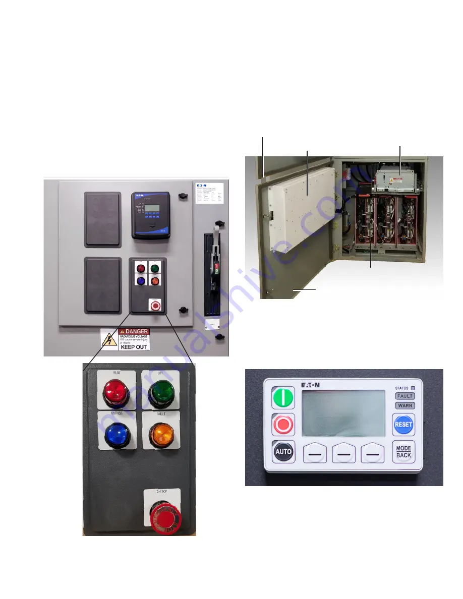
The following standard components are located on the front of the
low voltage door of the upper cell (see
Figure 3
).
•
Run-Off indicating lights - Denote the Main contactor status.
•
Bypass mode indicating light – After the motor is started and
reaches speed, the Bypass contactor closes to bypass the SCRs
in the soft starter. The bypass mode indicating light will illuminate
when the bypass contactor closes.
•
RVSS fault indicating light – In the event of a soft starter fault, the
RVSS fault indicating light will illuminate.
•
E-Stop - Removes control power from the Main contactor coil
circuit and signals the controller of an emergency stop condition.
•
Motor Protection Relay - Optional relay used to provide motor
protection while running on Bypass.
Figure 3. Low voltage components.
1.3 Lower cell
The lower cell consists of a welded frame with an upper tray for
the Bypass contactor and rails on the floor for the AMPGARD RVSS
truck assembly. The bottom door comes with an interlock tab that
prevents access to the lower cell until the isolation switch and
upper door have been opened before gaining access to the medium
voltage cell. The RVSS truck assembly and Bypass contactor are
shown racked into place in
Figure 4
.
Figure 4. Lower cell.
A second low voltage compartment is located on the lower cell
medium voltage door. The keypad operator interface is located on
the front of the low voltage door and is used to configure the RVSS
(see
Figure 5
). Refer to IB020003EN (AMPGARD RVSS Medium
Voltage Solid-State Soft Starter User Manual) for details on operating
the keypad.
Figure 5. Keypad, MUI Monitoring User Interface.
Bypass contactor
Door interlock tab
Low voltage
compartment
Medium
voltage door
RVSS truck
assembly


