4
Instruction Booklet
IB020004EN
Effective October 2020
Instructions for installation and maintenance
of the AMPGARD Reduced Voltage Soft Starter
EATON
www.eaton.com
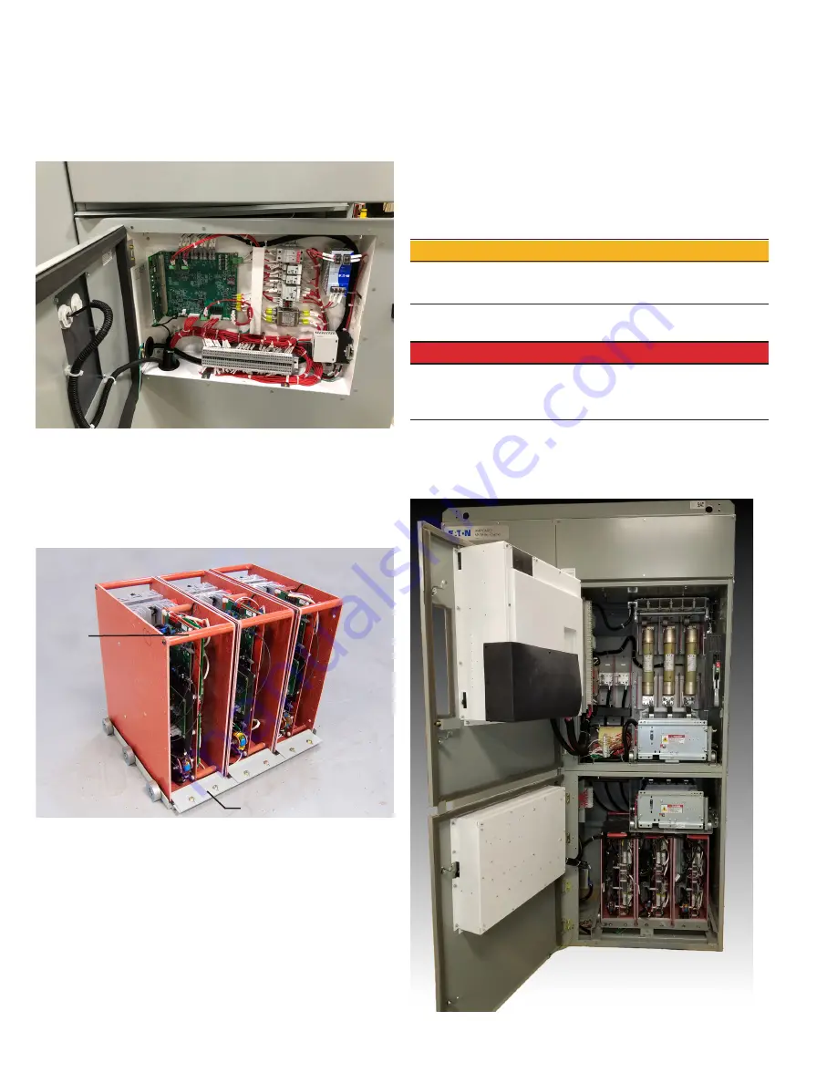
The control system for the RVSS is located in this low voltage
compartment. Components include the DSP control board, IOB
input-output interface board, C445 BCM Base Control Module and
MUI Monitoring User Interface (see
Figure 5
and
Figure 6
).
Figure 6. Control system boards.
1.4 RVSS truck
The RVSS power poles are mounted on an easy to remove, roll out
truck assembly. Additionally, each pole is individually removable and
replaceable without extracting the rest of the truck assembly. (see
Figure 7
).
Figure 7. RVSS truck.
2. Installation
Refer to IB48041 (Instructions for AMPGARD 400 ampere medium
voltage starter) for installation instructions. During installation,
the RVSS truck may be removed by following the instructions in
Section 2.1. Truck removal provides easy access to the cable area in
the lower cell for bottom entry starters and is required if dielectric
testing of the starter assembly is to be performed. To remove the
RVSS truck utilizing the provided ramp, a minimum clearance of 60
inches is required in front of the starter.
m
CAUTION
TO PREVENT DAMAGE TO THE RVSS, REMOVE THE RVSS TRUCK
INCLUDING ANY INPUT OR OUTPUT MV CONNECTIONS BEFORE
PERFORMING MEGGER/HIPOT TESTING.
2.1 RVSS truck removal
m
DANGER
HIGH VOLTAGE FROM RC SNUBBER STORED ENERGY MAY BE PRESENT
AFTER DISCONNECTING POWER TO THE UNIT. WAIT AT LEAST 15 MIN-
UTES BEFORE MAKING CONTACT WITH RVSS POWER POLES TO ALLOW
FOR PROPER VOLTAGE DISCHARGE.
1. Ensure the starter is de-energized by opening the isolation
switch and LOTO the feeder. Open the medium voltage doors
on the upper and lower cells (see
Figure 8
). (See IB48041 for
more information.)
Figure 8.
RVSS power poles
Bypass contactor
Pull bar
Pole hold-down plate


