Installation
Copyright © 2007-2018 Eaton Corporation. All Rights Reserved.
IPN 997-00012-07A1 July 2018
27
Step 4 - Connect load cables
1
Select load cable to suit the dc load currents and voltage drop requirements. Also
refer to the table of minimum cable sizes for specific MCBs on page
2
Route the load cables to the APS.
If the optional top cover is used then route the cables under the cable tie rod.
3
Terminate the load common cable(s) with an M6 crimp lug.
4
Connect the load common cable(s) on the common bar at the load termination
points. Tighten according to the Standard Torque Settings on page
5
Terminate the load live cable(s) at the load MCB(s).
The current rating of the MCBs must be derated to 75%.
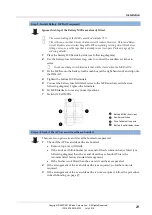
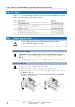
Ensure that the fuse fail detection wires are properly terminated as shown in the
following diagram.
6
Tighten the MCB terminal(s).
7
Switch OFF all MCBs.
Load MCB
Load live cable
Fuse fail detection wire (connected to fuse fail
alarm board)
Step 5 - Check terminations, secure cables and test insulation
1
Check all terminations are correct and are tightened.
2
Secure the cables with cable ties to the cable tie rod to ensure there will be no
strain on the terminals.
3
Test the insulation resistance of the cables.
Procedure complete

