41
6.5.1. Connection to I/O unit
Each I/O unit also has a BI/O bus. The light I/O units (ARC-EP10-2/2.0, ARC-EP10/2.0
ARC-EL3/2.0) can transmit trip information to the master unit or current I/O unit. The current
I/O unit (ARC-EC1/2.0) can receive the light information and send the current information to
other I/O units.
The following DI and DO connections are included in the standard delivery of ARC-
EP10/2.0 and ARC-EL3/2.0 units:
DI
X2-8
Zone
shift
1
2, 2
1, 3
4, 4
3
GND
X2-7
Trip out
X2-10
Trip information, 24 V dc
GND
X2-9
Trip
information
earth
The following DI and DO connections are included in the standard delivery of ARC-
EC1/2.0 units:
L>in
X2-8
Light input, 24-48 V dc
GND
X2-7
Light
input
earth
Trip out
X2-10
Trip information
GND
X2-9
Trip
information
earth
6.5.2. Connection to quenching device ARC-AT
The master unit ARC-EM/2.0 can be connected to an ARCON quenching device ARC-AT.
In the event of an arc fault the master unit generates a tripping pulse for the quenching de-
vice. The quenching device generates within 1ms a permanent 3-pole metallic short circuit.
Therefore the arc voltage subsides and the arc fault extinguishes.
After an arc fault switch-off the quenching device has to be replaced.
Figure: ARCON quenching device ARC-AT-B (schematic drawing)
(1) LED (green) displays operating mode
(2) LED (red) displays arc fault switch-off mode
(3)
Fixing
brackets
(4)
Busbar
connection
(5) Connection to master unit ARC-EM/2.0 (via connection cable ARC-CCAT)
(6)
Nameplate
ARCON
①
③
⑤
④
⑥
②
ARC-AT
Summary of Contents for ARCON 2.0 Series
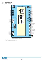
Page 51: ...51 7 6 Block diagram 7 6 1 ARC EM 2 0 Figure Connections of ARC EM 2 0...
Page 54: ...54 7 6 4 ARC EL3 2 0 7 6 5 ARC EC1 2 0...
Page 64: ...64 9 Construction 9 1 Dimensional drawings 9 1 1 ARC EM 2 0 panel and semi flush mounting...
Page 65: ...65 9 1 2 ARC EP10 2 2 0 din rail mounting...
Page 66: ...9 1 3 ARC EP10 2 0 din rail mounting 66...
Page 67: ...67 9 1 4 ARC EL3 2 0 din rail mounting...
Page 68: ...68 9 1 5 ARC EC1 2 0 din rail mounting...
Page 69: ...69 9 1 6 Fiber sensor mounting r min 50 mm...
Page 70: ...70 9 1 7 Point sensor mounting...
Page 82: ...82 10 Application examples 10 1 Applications 10 1 1 With a main busbar system...
Page 83: ...83 10 1 2 With two main busbar systems...
Page 84: ...84 10 1 3 With two main busbar systems and additional zone selection 4 zones...
Page 85: ...85...


