background image

24

负载状态

系统告警

UPS 带载时其输出线路将以流动图显示,否则输出线路变灰。单击负载图标可跳转至系统输出参数界
面查看具体负载信息,系统总的负载百分比以数字和刻度条的形式显示。

主页底部将实时显示系统的告警信息,当系统有多条告警时,告警信息将滚动显示。

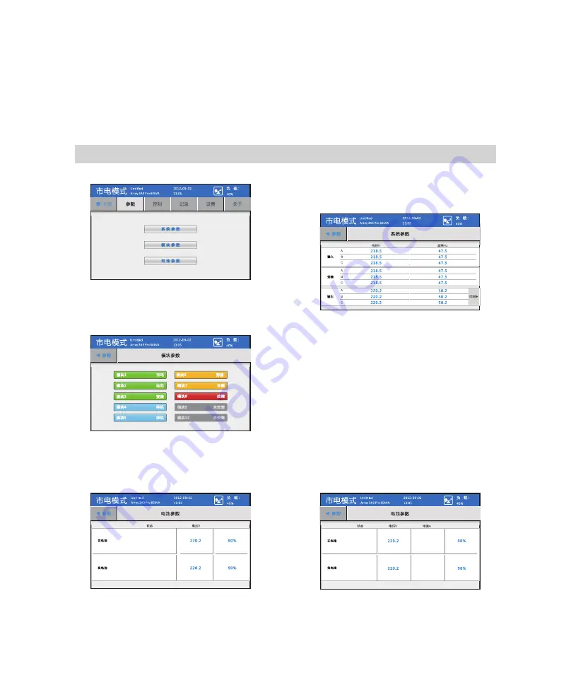
①点击主页菜单“参数”图标进入参数界面。

②点击“系统参数”,进入系统参数界面。若
系统参数界面是从主页点击“市电”或“旁路”
图标进入,则退出时直接返回主页。

④点击“电池参数”,进入电池参数界面。若从主页点击“电池”图标进入此界面,则退出时直接返
回主页。

③点击“模块参数”,进入模块参数界面。若
模块参数界面从主页点击 UPS 图标进入,则退
出时直接返回图标。

8.3 

参数

容量%

电池未接

电池未接

a. 电池电流禁止、后备时间禁止

b. 电池电流使能、后备时间禁止

容量%

电池未接

电池未接

45 0

.

45 0

.

Summary of Contents for ARRAY 3A3 Pro

Page 1: ...ARRAY 3A3 Pro UPS...

Page 2: ......

Page 3: ...UPS...

Page 4: ...1 ARRAY 3A3 Pro 2 www 95001111 com 95001111 010 95001111 106695001111 95001111 www 95001111 com www eaton com powerquality 2013...

Page 5: ...1 2 3 4 5 UPS 6 7 8 9 UPS UPS 1 2 UPS UPS 3 Eaton 1 UPS 2 3 4 A B C D E 5 6 7...

Page 6: ...1 a 0 40 20 90 b c 2 UPS 25 55 UPS 0...

Page 7: ...UPS UPS UPS UPS 01 03 05 08 11 16 18 21 31 33 35 37 39 40 41...

Page 8: ...1 1 1 ARRAY UPS 3A3 Pro UPS 1 2 1 3 3A3 Pro UPS ARRAY UPS UPS AR RAY UPS UPS UPS UPS 3A3 Pro UPS UPS UPS UPS 19 2 UPS UPS UPS 15kVA UPS UPS 150kVA UPS UPS...

Page 9: ...2 3A3 Pro UPS 3A3 Pro UPS 1 4 1 5 GB 4943 1 2011 1 YD T 1095 2008 UPS EMC C2 3A3 Pro UPS UPS UPS 7 UPS EATON 400 889 3938 24 IEC 62040 2 2005 C3...

Page 10: ...3 2 1 1 2 1 2 2 2 3 2 3 4 2 4 5 2 5 2 2 2 1 2 3 2 4 2 5...

Page 11: ...4 2 8 2 2 2 6 2 7 UPS 1 2 6 2 UPS 2 7 3 UPS 2 8...

Page 12: ...5 3 1 UPS 120kVA 3 1 LCD UPS UPS 3 2 150kVA...

Page 13: ...6 3 4 120K 3 6 150K 3 3 120K 3 5 150K...

Page 14: ...7 3 2 UPS 3 7 3 10 3 8 3 9...

Page 15: ...4 UPS 1000 UPS UPS M 1000 1500 2000 2500 3000 3500 4000 4500 5000 100 95 91 86 82 78 74 70 67 5 3A3 Pro UPS UPS 6 3A3 Pro UPS 32 40 3 UPS UPS 40 38 36 34 32 100 95 90 85 80 7 3A3 Pro UPS UPS Y 8 3A3 P...

Page 16: ...9 1 2 3 M8 4 2 4 2 4 1 4 3 4 3 4 UPS 4 3 D1 D2 D3...

Page 17: ...10 5 UPS 6 4 4 7 4 6 UPS UPS 4 5 8 M6 4 5 9 UPS 4 4 4 5 3U 2 2U...

Page 18: ...AWG 2 16mm2 2 2AWG 2 35mm2 2 6AWG 2 16mm2 2 2AWG 2 35mm2 2 6AWG 2 16mm2 2 5 4AWG 2 25mm2 2 4AWG 3 25mm2 3 4AWG 2 25mm2 2 4AWG 3 25mm2 3 4AWG 2 25mm2 2 6 4AWG 2 25mm2 2 2AWG 3 35mm2 3 4AWG 2 25mm2 2 2A...

Page 19: ...3 80A 250VAC 3 80A 500VDC 3 3 120A 250VAC 3 120A 250VAC 3 120A 500VDC 4 3 160A 250VAC 3 160A 250VAC 3 160A 500VDC 5 3 200A 250VAC 3 200A 250VAC 3 200A 500VDC 6 3 240A 250VAC 3 240A 250VAC 3 240A 500VD...

Page 20: ...13 UPS 1 1 UPS N 2 3A3 Pro UPS 32 40 40 3 UPS UPS 5 4 5 2 5 3 N...

Page 21: ...14 2 1 5 6 2 UPS 5 7 3 4 5 6 5 7 UPS 5 4 5 5 UPS...

Page 22: ...15 1 5 8 2 UPS 5 9 3 5 8 5 9 150kVA 1 2 5 10 3 UPS 5 11 4 5 10 UPS 5 11 UPS...

Page 23: ...UPS UPS N X N X UPS UPS X UPS UPS 3A3 Pro UPS 1 10 3A3 Pro UPS N X 25kVA 1 UPS 2 2 60kVA 54kW 27kW UPS X 2 2 3 UPS 6 1 N X 6 2 UPS 3A3 Pro UPS UPS UPS N X UPS kVA kW 2 0 30 27 0 2 1 30 27 1 2 2 30 27...

Page 24: ...17 2 UPS 1 2 UPS UPS UPS 3 6 3 4 ON 6 2 6 1 6 3 6 2 1 UPS 1 UPS 6 1 OFF 6 2 2 UPS UPS 5 UPS UPS UPS UPS...

Page 25: ...18 LCD UPS LCD UPS UPS UPS LCD UPS 7 1 7 2 7 1 LCD 7 1 1 Array 3A3 Pro xxKVA CSB 3s Array 3A3 Pro 60kVA...

Page 26: ...19 7 2 UPS 1 1 ON 6 2 2 UPS 7 3 6 3 4 5 7 4 1 ENTER 1111 1234 7 3 7 4...

Page 27: ...20 1 UPS UPS 2 EPO 3 4 7 3 10 UPS UPS ENTER 1 2 1111 1234...

Page 28: ...21 8 1 UPS UPS UPS UPS ID ID English 14 UPS LCD LCD LCD 13 10 10 5 11 3V...

Page 29: ...22 8 2 UPS 1 2 CSB UPS YYYY MM DD XCP XCP 30 USB BUS 6 1 2 3 4 5 6 9 10 7 8 Array 3A3 Pro 60kVA 7 5...

Page 30: ...23 UPS 1 2 3 1 2 3 1 2 UPS 3 UPS 4 UPS 10 UPS...

Page 31: ...24 UPS UPS 8 3 a b 45 0 45 0...

Page 32: ...25 7 2 7 3 1111 1234 8 4 35 35 a b 35 35 45 0...

Page 33: ...26 UPS 8 5 ID ID 0 65535...

Page 34: ...27 8 6 YYYY MM DD hh mm ss xxx xxx ID ID 0 65535 CSB UPM1 UPM10 0 65535 14 8 6 1...

Page 35: ...28 10 60min 0 9000s 10s LCD 1 100 13 400 830 3938 800 830 3938 13666666666 13888888888...

Page 36: ...29 8 6 2 45 18 18 Panasonic_100AH 15 15 5 5 10 10 242V 198V...

Page 37: ...30 XCP USB BUS 8 7...

Page 38: ...31 UPS 400 889 3938 UPS 1 1 UPS UPS 2 9 1 1 UPS 2 3 UPS 9 1 UPS 9 2 9 3 9 1...

Page 39: ...32 3 OFF 9 5 4 9 6 5 LCD 9 4 9 5 9 6 UPS LCD UPS 3 ON 9 2 4 UPS OFF 9 3 5 UPS OFF 9 3 9 2 2 UPS 1 UPS ON 2 UPS UPS ON 9 4...

Page 40: ...33 1 2 3 4 UPS UPS 10 1 ARRAY UPS Intelligent Slot EPO UPS 10 1 10 1 10 2 EPO Emergent Power Off EPO UPS EPO UPS 10 2...

Page 41: ...RAY 3A3 Pro RS232 USB UPS UPS 3 USB RS232 USB RS232 UPS AS400 AS400 UPS NMC Internet UPS CMC MODBUS UPS 1 UPS 2 3 USB RS232 USB RS232 PC 4 WinPower USB RS232 AS400 NMC CMC 400 889 3938 10 4 UPM 5m 2m...

Page 42: ...35 5 4 LCD UPS UPS 30s UPS 30s 1 UPS UPS 3 UPS 2 UPS UPS 1 3A3 Pro UPS 1 2 LCD 11 1 LCD 3A3 Pro UPS 11 2 UPS...

Page 43: ...36 2 1 LCD 6 LCD 11 3...

Page 44: ...Hz 50 1 0 5 Hz 10 110 130 UPS Up to 94 124 300VAC 214 520VAC 40 70Hz 0 99 187 253VAC 323 437VAC 12 1 12 2 62dB 0 40 20 90 1000m 25 55 12 3 12 1 3 16 17 18 19 20 192VDC 204VDC 216VDC 224VDC 240VDC 3 5...

Page 45: ...H mm kg 2 0 60kVA 600 1050 2030 200 2 0 90kVA 600 1050 2030 230 2 0 90kVA 600 1050 2030 230 2 0 120kVA 600 1050 2030 265 2 0 120kVA 600 1050 2030 265 2 0 150kVA 600 1050 2030 275 483 194 131 9 UPS 440...

Page 46: ...39 24 400 889 3938 www eaton com powerquality upsservice eaton com...

Page 47: ...40 _ _ 1 4 2 1 2 3 4 5 Fault...

Page 48: ...2 24Ah 3 24Ah 4 24Ah 5 24Ah 6 24Ah 7 24Ah 8 15kVA 30kVA 45kVA 60kVA 75kVA 90kVA 105kVA 120kVA 135kVA 150kVA 38Ah 1 38Ah 2 38Ah 3 38Ah 4 38Ah 5 38Ah 6 38Ah 7 38Ah 8 15kVA 30kVA 45kVA 60kVA 75kVA 90kVA...

Page 49: ...2 65Ah 3 65Ah 4 65Ah 5 65Ah 6 65Ah 7 65Ah 8 15kVA 30kVA 45kVA 60kVA 75kVA 90kVA 105kVA 120kVA 135kVA 150kVA 75Ah 1 75Ah 2 75Ah 3 75Ah 4 75Ah 5 75Ah 6 75Ah 7 75Ah 8 15kVA 30kVA 45kVA 60kVA 75kVA 90kVA...

Page 50: ...0Ah 3 100Ah 4 100Ah 5 100Ah 6 100Ah 7 100Ah 8 15kVA 30kVA 45kVA 60kVA 75kVA 90kVA 105kVA 120kVA 135kVA 150kVA 120Ah 1 120Ah 2 120Ah 3 120Ah 4 120Ah 5 120Ah 6 120Ah 7 120Ah 8 15kVA 30kVA 45kVA 60kVA 75...

Page 51: ...uctions in the manual and on the machine should be strictly followed and this user manual should be kept properly for future reference Do not attempt to operate the UPS until reading through all safet...

Page 52: ...cking System and input the supervision code Tel inquiry Call 95001111 to check you may call 010 95001111 and follow the instructions to enquire the identification Message inquiry send text message to...

Page 53: ...6 Dry and non conductive items should be used for cleaning 7 In case of a re hazard dry powder extinguisher should be used properly Using liquid re extinguisher may result in electric shock hazard 8...

Page 54: ...expertise can carry out the maintenance of accumulator batteries 3 Replacement of accumulator batteries requires a match of same type and model with equal quantity 4 As accumulator batteries may cont...

Page 55: ...Chapter 6 Adding Reducing Replacing modules online 17 Chapter 7 Operation 19 C h a p t e r 8 M e n u Commands 23 Cha pt e r 9 Maintenance 35 Chapter 10 Communication interface 37 Chapter 11 Troublesho...

Page 56: ...performance double conversion and pure online UPS Like other products of the ARRAY UPS series the 3A3 Pro UPS adopts the design of drawer style and high intelligence modules Every UPS module is a thre...

Page 57: ...played on a large LCD screen which makes the UPS operation simple and easy 3A3 Pro UPS is designed to prevent almost all of the power problems such as power surges high voltage spikes switching transi...

Page 58: ...re should be 1 one user manual 2 Accessory includes screws cable tie and two keys 1 Disassemble the top cover cut off the packing tape by scissors and remove the top cover Fig 2 1 2 Disassemble the Si...

Page 59: ...the packing strap and open the carton see Fig 2 6 2 Lift the foam on the UPS module upward to remove them see Fig 2 7 3 Take out the UPS module see Fig 2 8 Note the UPS is heavy It requires two people...

Page 60: ...UPS Fig 3 2 Top view of cabinet with upper wire outlet holes the right figure containing of cable clamp Chapter 3 Exterior Appearance PDU optional Communication interface LCD panel UPS module Fig 3 1...

Page 61: ...20kVA rear view of cabinet with upper wire outlet holes Fig 3 5 150kVA rear view Fig 3 4 120kVA rear view of cabinet with lower wire outlet holes Fig 3 6 150kVA rear view of cabinet with lower wire ou...

Page 62: ...7 lndicator Position lock Fig 3 7 Front view Fig 3 8 Rear view Fig 3 9 Top view 3 2 Exterior gure of the module It requires two people for transportation due to its weight Fig 3 10 PDU front view...

Page 63: ...tery pack consists of 32 40 batteries in series which is divided into two parts by a neutral wire connecting to the middle of the pack Therefore there are altogether three wires connected with the UPS...

Page 64: ...height of adjustable feet Fig 2 4 2 Push the cabinet to the predetermined location and adjust the height of adjustable feet by wrench to set the casters in vacant position 3 Fix the adjustable feet wi...

Page 65: ...he above 4 6 steps to install all of the UPS modules into the cabinet in sequence Fig 4 5 8 Install the PDU module optional Remove the plastic blind plate and adjust the position of caged nuts fix the...

Page 66: ...s no need to change the wire diameter when expanding the capacity of the UPS If the quantity of the UPS modules installed is less than the capacity of the UPS cabinet the user can also choose the wire...

Page 67: ...and current should be taken into consideration when selecting NFB And it is recommended to select it according to the real capacity of the UPS the modules installed to ensure effective protection Ple...

Page 68: ...the positive and negative wires of the battery pack The battery cables should connect to a DC breaker firstly and then it can be connected to the terminal block of the UPS Please refer to the followi...

Page 69: ...odent resistant board Connection cover board Teminal block Wire connection hole Wire outlet cushion rubber Fig 5 3 Wiring location of cabinet with upper wire outlet holes without the wire outlet cover...

Page 70: ...to the cable clamp with cable ties Fig 5 6 Fig 5 7 Wire connection cabinet with lower wire outlet holes 1 Remove the front terminal block cover and bottom connection cover board see Fig 5 8 2 Connect...

Page 71: ...the rodent resistant board according to the marks the copper bar marks are shown as Fig 5 10 3 Remove the front terminal block cover connect the UPS output wires to the corresponding copper bars ac c...

Page 72: ...ged online without affecting the UPS running 6 1 Options supplied by the N X parallel redundancy system The 3A3 Pro UPS can be installed from 1 up to 10 3A3 Pro UPS modules in its cabinet and the user...

Page 73: ...d put it on the ground or some other temporary supports gently Fig 6 1 Fig 6 2 2 Adding the UPS Module Online 1 Remove the cover plate located in the position where the module will be installed 2 Two...

Page 74: ...Fig 7 2 N orm al 40 Load System status Display the current machine status Machine name It is defined by users If the user has several cabinets they can be distinguished by setting names Machine model...

Page 75: ...of status bar Color Description Blue The modes that the system is in Shutdown Standby Normal Converter Battery sufficient battery capacity and Battery Test sufficient battery capacity Orange The modes...

Page 76: ...tatus click the Control button on the Home menu bar to directly en ter the system control interface If the control password is set to the enabled status the password is required to enter the system co...

Page 77: ...message on op eration prohibited as follows Button Message on operation prohibited Shutdown to bypass 1 Bypass is forbidden on Converter Mode 2 Bypass is abnormal cannot go to Bypass Run Test Last Te...

Page 78: ...negative batteries Set battery current detection as disable in Setting Service Battery Configuration then there is no content of battery current displayed in Battery Parameter Interface Control Syste...

Page 79: ...limit voltages for bypass This setting can be undergone only under Standby Mode or Bypass Mode System Mode Set the System Mode The Normal Mode and Converter Mode are optional Minislot Baudrate CSB pan...

Page 80: ...ng Battery Bypass Meters Home 40 UPM1 UPM2 UPM3 UPM4 UPM5 UPM6 9 10 Normal UPM7 UPM8 Settings Logs Load Normal Control About Utility Bypass Battery Load Normal Normal Normal Normal Normal Normal Norma...

Page 81: ...By clicking this icon it can turn to battery parameter interface to view the battery information UPS module status The statuses for each UPS module can be displayed with a maximum of 10 module icons...

Page 82: ...e icon when exiting 218 5 47 5 218 5 218 5 47 5 47 5 218 5 47 5 218 5 218 5 47 5 47 5 220 2 50 2 220 2 220 2 50 2 50 2 Inupt Voltage V Frequency Hz Details Bypass Output Meters Normal Load System Mete...

Page 83: ...run battery test OK Cancel 8 4 Control Click the Control icon on the Home menu to enter the login interface The control password or user password or service password is required to enter the system co...

Page 84: ...s interface 8 5 Logs Active Event System Log C l e a r L o g Load Normal Meters Meters Home Home Control Control Settings Settings Logs Logs About About Click the Clear Log and type the service passwo...

Page 85: ...N a m e B a t t e r y T e s t S c r e e n S a v e r T i m e L a m p T e s t C o n t r o l P a s s w o r d L C D B a c k l i g h t C o n f i g P a s s w o r d S e r v i c e P h o n e Normal Load Item...

Page 86: ...t self test time is 10s 8 6 1 Con guration Machine Name Please input machine name 3A3 Pro S a v e Normal Load Config Config Language E n g l i s h S a v e Normal Load Y M D 16 46 38 2012 11 15 m h s S...

Page 87: ...13 characters 400 830 3938 800 830 3938 Service Phone 13666666666 13888888888 S a v e Service Phone Load Config Normal Phone 1 Phone 2 Phone 1 Phone 2 Hot Line Config Password Old Password Enable Disa...

Page 88: ...et 0V System Mode can only be set on Standby Mode System Mode Normal Mode Converter Mode S a v e Load Normal Service Enter the Minislot Baudrate interface to set the baud rate for the three slots Ente...

Page 89: ...V 360V 360V 360V 360V BUS Volt BUS BUS Export Log Export log to USB File path DatabaseExport Data Loggers File name HistoryLog 3A3 Pro HMISave csv _ _ _ Load Normal Service Reset Password Reset Contro...

Page 90: ...electric shock may occur 9 2 Service Methods If the UPS fails for unkown reasons do not operate the UPS contact the nearest service site or the distributor or call customer service hotline at 400 889...

Page 91: ...maintenance bypass 1 Set the battery switch and the input breakers of the UPS modules to ON position 2 After all the UPS modules have transferred to the bypass mode set the output switch of the UPS t...

Page 92: ...n monitor the UPS operation status by computer easily see Fig 10 1 Fig 10 1 Fig 10 2 10 2 EPO The EPO Emergency Power Off switch is green and located at the right upper part of the rear panel which is...

Page 93: ...he UPS when installing the intelligent cards 2 Remove the cover plate prior to the installation and keep it for future use 3 The USB RS232 card provides both USB port and RS232 port users may choose o...

Page 94: ...breaker is in the position of OFF Solution set the position lock to the position of locking and set the input breaker in the position of ON 11 2 Common problems on UPS module Problem 1 the slid modul...

Page 95: ...ms on Battery and charger Problem 1 no charging voltage and charging current in line mode Possible cause battery is detected to be disconnected when starting the unit and the charger is shut down Solu...

Page 96: ...ncy tolerance 50 1 0 5 Hz in line mode 50 1 0 5 Hz in battery mode Overload time 10 min 110 load 130 UPS efficiency Up to 94 12 1 3 Battery rated voltage Unilateral battery number of 16 17 18 19 20 Po...

Page 97: ...es 2 0 meter tall 600 1050 2030 230 90kVA UPS cabinet with lower wire outlet holes 2 0 meter tall 600 1050 2030 230 120kVA UPS cabinet with upper wire outlet holes 2 0 meter tall 600 1050 2030 265 120...

Page 98: ...Three year warranty including batteries purchased from the company 24 hour toll free hot line service 400 889 3938 Nationwide warranty Technical support on our web site Website www eaton com powerqua...

Page 99: ...trigger Fault LED flashing and BUZZER 2 Buzzer stops beeping and fault LED stops flashing once enters to Logs Active Event screen No Working condition LED Display BUZZER Normal Battery Bypass Fault 1...

Page 100: ...attery configuration table the blank columns in the table indicate configuration prohibition and the filled columns indicate the permitted number of the battery packs 1 24Ah battery configuration tabl...

Page 101: ...ttery Pack Power 65Ah 1 65Ah 2 65Ah 3 65Ah 4 65Ah 5 65Ah 6 65Ah 7 65Ah 8 15kVA 30kVA 45kVA 60kVA 75kVA 90kVA 105kVA 120kVA 135kVA 150kVA Battery Pack Power 75Ah 1 75Ah 2 75Ah 3 75Ah 4 75Ah 5 75Ah 6 75...

Page 102: ...ack Power 100Ah 1 100Ah 2 100Ah 3 100Ah 4 100Ah 5 100Ah 6 100Ah 7 100Ah 8 15kVA 30kVA 45kVA 60kVA 75kVA 90kVA 105kVA 120kVA 135kVA 150kVA Battery Pack Power 120Ah 1 120Ah 2 120Ah 3 120Ah 4 120Ah 5 120...

Page 103: ...614 00789 03...

Reviews: