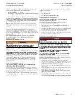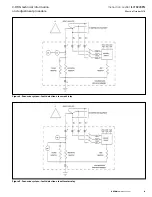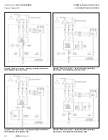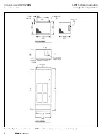
4
Instruction Leaflet
IL019226EN
Effective October 2018
C-HRG technical information
and adjustment procedure
EATON
www.eaton.com
Operation
Indication and alarm circuits
Indication and alarm circuits
When a fault is detected by means of either current or voltage,
an adjustable time relay is provided in order to override transients.
There may be an extra timer in the control circuit. When the time
delay has been exceeded, the green “normal” light will turn off, the
red “ground fault” light will turn on, and the ground alarm contacts
will transfer. If equipped with the optional alarm horn, it will sound.
When the fault is cleared, the current/voltage relay will reset. If
the reset control is set on “auto,” the lights will return to “normal”
on, “ground fault” off. If the reset control is set on “manual,” the
lights and relay contacts will remain latched until the operator turns
the reset control to “reset.” The lights will then return to “normal”
on, “ground fault” off. The system can be reset only if fault has
been cleared.
During a fault, the optional alarm horn can be silenced at any time by
using the “alarm silence” pushbutton. It will not resound until either
the system is reset, or the re-alarm timer expires. The re-alarm timer
is activated by the “alarm silence” control. If the horn has been
silenced but the fault has not been cleared, the timer will run. It has
a range of 2–48 hours. When the timer runs down, the horn will
resound, alerting maintenance personnel that the fault has not been
cleared.
Test circuit
A test circuit is provided to allow the user to quickly determine
that the system is working properly. The test circuit will operate
only under normal conditions and will not allow testing if the
system is sensing a fault. A separate grounding resistor is provided
and is connected to a relay operated by the “test” position and
mode selector switch. (The selector will spring-return to “normal”
when released.) The relay’s contact grounds phase B through the
resistor, causing ground current to flow. The system then reacts
as it would under actual system ground conditions. The lights turn
on, alarm contacts transfer, and the (optional) alarm horn sounds.
Because periodic testing is the only assurance of continuing
reliability, a program of regular testing and maintenance is strongly
recommended.
Pulser circuit
The pulser circuit offers a convenient means to locate the faulted
feeder and trace the fault to its origin. The pulser is available any
time a fault has been detected (in “test” mode, the pulser turns
on automatically). Turn the mode selector switch from “normal”
to “pulse” to activate the pulser circuit. The pulse intervals are
controlled by a recycle timer, which has a range of 1–10 seconds
“on” and 1–10 seconds “off.” (The recommended setting is
30 pulses/minute—1 sec on, 1 sec off.) The white “pulse” light
flashes on and off corresponding to the on-off cycles of the pulser
contactor. The pulser contactor switches a bank of resistors on
and off, allowing a momentary increase in the ground current
(approximately a 5 A current pulse above the ground current).
Short circuiting terminal block
DANGER
HIGH VOLTAGE!
WILL CAUSE DEATH, BODILY INJURY, OR EQUIPMENT DAMAGE.
DO NOT OPEN-CIRCUIT A CURRENT TRANSFORMER UNDER LOAD.
If the current transformer has primary current passing through it,
do not disconnect any devices on its secondary side without first
shorting across the transformer’s secondary terminals. If open-
circuited under load, a very high voltage will develop instantaneously
across the disconnection point, placing the operator and equipment
in danger.
This is the first device in the current circuit on the secondary side
of the current transformer and is provided to allow a convenient
means for short circuiting the current transformer’s secondary
side when testing, calibration, or repairs are required. To short
the current transformer secondary, move the shorting pins from
storage positions at the corners of the terminal block to both
current connections. Devices in the current circuit may be safely
disconnected only after the current transformer secondary is
properly shorted.


