background image


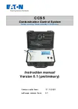
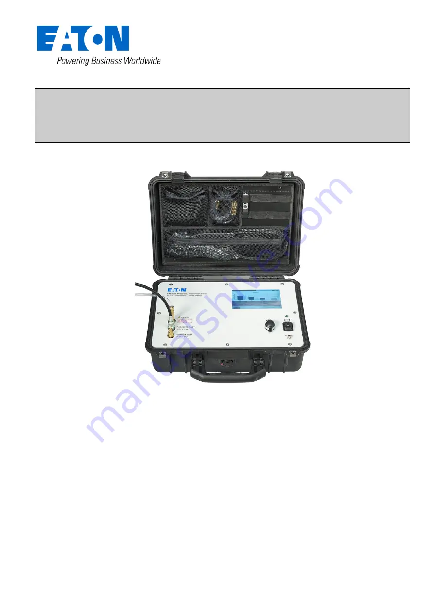
CCS 5 

Contamination Control System 

Particle co Water satu Temperature  


Instruction manual 

Version 0.1 (preliminary) 


Version valid from: 

17.11.2021 


software version from:  

0.1 


Summary of Contents for CCS 5

Page 1: ...CCS 5 Contamination Control System Particle counting Water saturation Temperature Instruction manual Version 0 1 preliminary Version valid from 17 11 2021 software version from 0 1...

Page 2: ...o the suction operating mode min 0 2 bar 10 2 4 Electrical connection 10 2 4 1 Mains operation 10 2 4 2 Battery operation 11 2 5 Operation with the CCS 5 software 12 2 5 1 Main menu 12 2 5 2 measureme...

Page 3: ...lic plan 39 7 3 Measurement principle 39 7 3 1 Laser sensor Particle Counter for CCS 5 39 7 3 2 Water sensor 40 7 4 Cleanliness classes according to ISO 4406 99 41 7 5 Cleanliness classes according to...

Page 4: ...he system and its operability are marked with the following signal word NOTICE describes the correct way of handling the device The above signal words can be combined with the safety symbols or the wa...

Page 5: ...imity switches and so on Error in control Failure of components due to for example excessive system pressure material fatigue Contamination of the hydraulic fluid Thrown or bursting of parts May be a...

Page 6: ...is prevents the entry of water into the CCS 5 Look at the hoses while closing the housing cover 1 6 Intended applications The CCS 5 is a mobile diagnostic system meant for continuous monitoring and co...

Page 7: ...y microscope If the laser sensor is blocked e g showing low classification code please take the following steps Attempt to flush the system with clean NAS 4 or ISO 16 13 9 or better low viscosity flui...

Page 8: ...g system and cause a significantly higher abrasion an increase of the failure risk of components as well as malfunctions The CCS 5 is for the continuous monitoring and condition analyses of hydraulic...

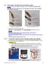
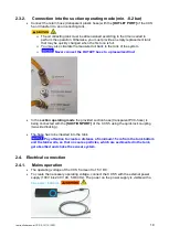
Page 9: ...f the ports at the CCS 5 the hydraulic system and the hoses The ports must be cleaned before using 2 3 1 Connection into the pressure operating mode max 350 bar Connect the return hose transparent pla...

Page 10: ...se to a pressurized line In the suction operating mode the provided suction hose transparent PVC hose is being connected with the SUCTION PORT of the CCS 5 using the quick lock coupling two sided lock...

Page 11: ...polymer battery with internal battery charger is integrated in the CCS 5 It allows for an approximate continuous operating time of 2 4 hours depends on the viscosity of the testing fluid The CCS 5 sw...

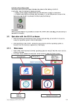
Page 12: ...ble to connect the CCS 5 with a car plug the accessory is available on request 2 5 Operation with the CCS 5 software After connecting the necessary hoses power and switching on the CCS 5 the unit is r...

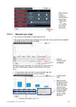
Page 13: ...ware update System information Showing the software version calibration date system date time charging current of the battery 2 5 2 measurement For the measuring in the appropriate operating mode depe...

Page 14: ...cation is entered test is automatically used Measure mode Select the measure mode single continuous cyclic by choosing the check box Report standard It is possible to display the measurements accordin...

Page 15: ...15 By touching the filed a new window with all recorded fluids will show up to be selected Then confirm the selected fluid then the menu will be automatically switched to the previous menu The selecte...

Page 16: ...ndard ISO 4406 99 NAS 1638 SAE AS 4059 Start the measurements with Start The flush process runs before the measurement it takes from 15 seconds to 300 seconds based on the selection in the setup menu...

Page 17: ...perform a flushing of the CCS 5 with cleaned mineral oil filtrated H22 for several minutes after finishing the measurements 2 5 2 2 Measure type continuous This mode is to accomplish the continuous me...

Page 18: ...he date of start is displayed The measurements are continued until they get stopped with button STOP To continue the measurement just press the button START The numbers of each measurement and the dat...

Page 19: ...pe in report standard Select the flush Time in seconds Select a fluid type if needed Select the desired cycle period in hour with buttons Select the desired cycle numbers 2 100 with buttons Confirm th...

Page 20: ...ta The measurements in the permanent data storage persist until they are deleted manually or the maximum quantity of the storage data is exceeded o Max 100 measurements of each measure type can be sav...

Page 21: ...s single or continuous or cyclic The selected menu tab is highlighted white While a USB stick is inserted the buttons transfer to USB will show The saved files will be indicated according date and tim...

Page 22: ...int 329 is chosen the saved data is being shown below swiping the charts to left or right to choose a different measurement point it is recommended to use a stylus for resistive touch panel By press t...

Page 23: ...ty 2 GB FAT 16 insert the USB stick in the USB connection port of the CCS 5 When the USB stick is recognized by the operating system a USB logo will show on the screen in the menu file system select t...

Page 24: ...ly when it is confirmed This function is meant for setting the real time clock integrated in the device Day month hour and minute are separately adaptable and are getting transferred to the real time...

Page 25: ...e and load it to a USB stick make sure the software is on the root folder Then insert the USB stick to the CCS 5 The USB logo will show if the USB stick is recognized The update will be executed by pr...

Page 26: ...ecked Software version current data time battery voltage charging current system temperature and the data when the last calibration was carried out The validity of the calibration certificate is 12 mo...

Page 27: ...manager software on an external computer is necessary The data manager enables the data transfer to a MS Excel data sheet Execute CCS 5 data manager program installation setup exe from the provided U...

Page 28: ...USB stick will be loaded automatically and displayed in the table in the data manager The transferred data can be I Presented graphically II Exported in a MS EXCEL chart III Printed as a report I For...

Page 29: ...r NAS1638 can be chosen Back to the previous menu by using CLOSE Export in a Excel data sheet by using the button EXCEL For further processing the data all standard functions in MS EXCEL are available...

Page 30: ...Instruction manual CCS 5 15 10 2021 30 Report printing For exiting the data manager software use Button EIXIT...

Page 31: ...generated saturation characteristic line is specifically made for your type of fluid Saturation characteristic lines for special oils can be provided on request 4 1 2 Display of the fluid type and ppm...

Page 32: ...Instruction manual CCS 5 15 10 2021 32 Example of a provided saturation characteristic curve 0 200 400 600 800 1000 1200 30 10 10 30 50 70 90 Water content in ppm mg kg Temperature in C...

Page 33: ...the measurement channel usually the measurement results stay at 4 4 4 4 or 0 0 0 0 the indicates that the screen is full with dirty it has to be cleaned or renewed 5 1 Pressure INLET Detach all conne...

Page 34: ...sing a 19mm wrench 5 2 Suction INLET Detach all connections to the CCS 5 Open the INLET measurement point using a 17mm wrench Take the screen from the INLET out using a tweezer Then insert the new scr...

Page 35: ...Instruction manual CCS 5 15 10 2021 35 Put a new copper ring ordering no 306330 on the port Then Screw the INLET connector tight to 10 NM using a 17mm wrench...

Page 36: ...is calibrated on delivery as well The validity of the calibration certificate is 12 months Eaton recommends a calibration interval of one year For the secondary calibration the CCS 5 the unit is to be...

Page 37: ...aturation 0 100 temperature 30 70 C 22 158 F Suction operating range 0 2 0 2 bar 2 9 2 9 PSI Pressure operating range 1 5 350 bar 22 5 000 PSI Viscosity range 10 400 mm s 45 1854 SUS Operating tempera...

Page 38: ...f each max 100 measurements Further serial equipment external power supply unit high pressure hose PVC discharge hose PVC suction hose data manager USB Stick with the software Data Manager Display 7 i...

Page 39: ...le blocks this light blockade the photodiode will detect a decrease in received light depending on the particle s size and the electric voltage of the photodiode will decrease as well Troubles or faul...

Page 40: ...nt of the fluid in all measuring programs should be prevent from alterations of the measurement results 7 3 2 Water sensor The water sensor is a capacitive sensor As a dielectric between two electrode...

Page 41: ...ness class doesn t depend on the particle size Example of presenting 20 16 12 Analysis volume 1 ml Cleanliness class Number of particles Up to and including 26 320000 640000 25 160000 320000 24 80000...

Page 42: ...022 0 004 0 001 0 0 0 250 0 044 0 008 0 002 0 1 0 5 0 089 0 016 0 003 0 001 2 1 0 178 0 032 0 006 0 001 3 2 0 356 0 063 0 011 0 002 4 4 0 712 0 126 0 022 0 004 5 8 1 425 0 253 0 045 0 008 6 16 2 85 0...

Page 43: ...D E F 000 195 76 14 3 1 0 00 390 152 27 5 1 0 0 780 304 54 10 2 0 1 1560 609 109 20 4 1 2 3120 1220 217 39 7 1 3 6250 2430 432 76 13 2 4 12500 4860 864 152 26 4 5 25000 9730 1730 306 53 8 6 50000 1950...

Page 44: ...shooting and the repair process To check your warranty and to answer questions by phone we need the serial number and the date of purchase of the instrument 7 9 Software license and copyright EATON GP...

Page 45: ...658 3 High pressure hose 313742 4 PVC hose DR 8x1 316875 5 Quick connector Rectus 21K KO08 MPX 335908 6 USB stick 2GB fat16 337627 7 Calibration certificate annual maintenance calibration at Eaton Tec...

Page 46: ...list of Eaton s filtration products 2012 Eaton Corporation All Rights Reserved All trademarks and registered trademarks are the property of their respective owners Litho USA All information and recom...

Page 47: ...Instruction manual CCS 5 15 10 2021 47...

Reviews: