56
Mounting- and Operating Instruction CEAG DualGuard-S
40071860347 January 2020 www.ceag.de
20 ACU DG Modul
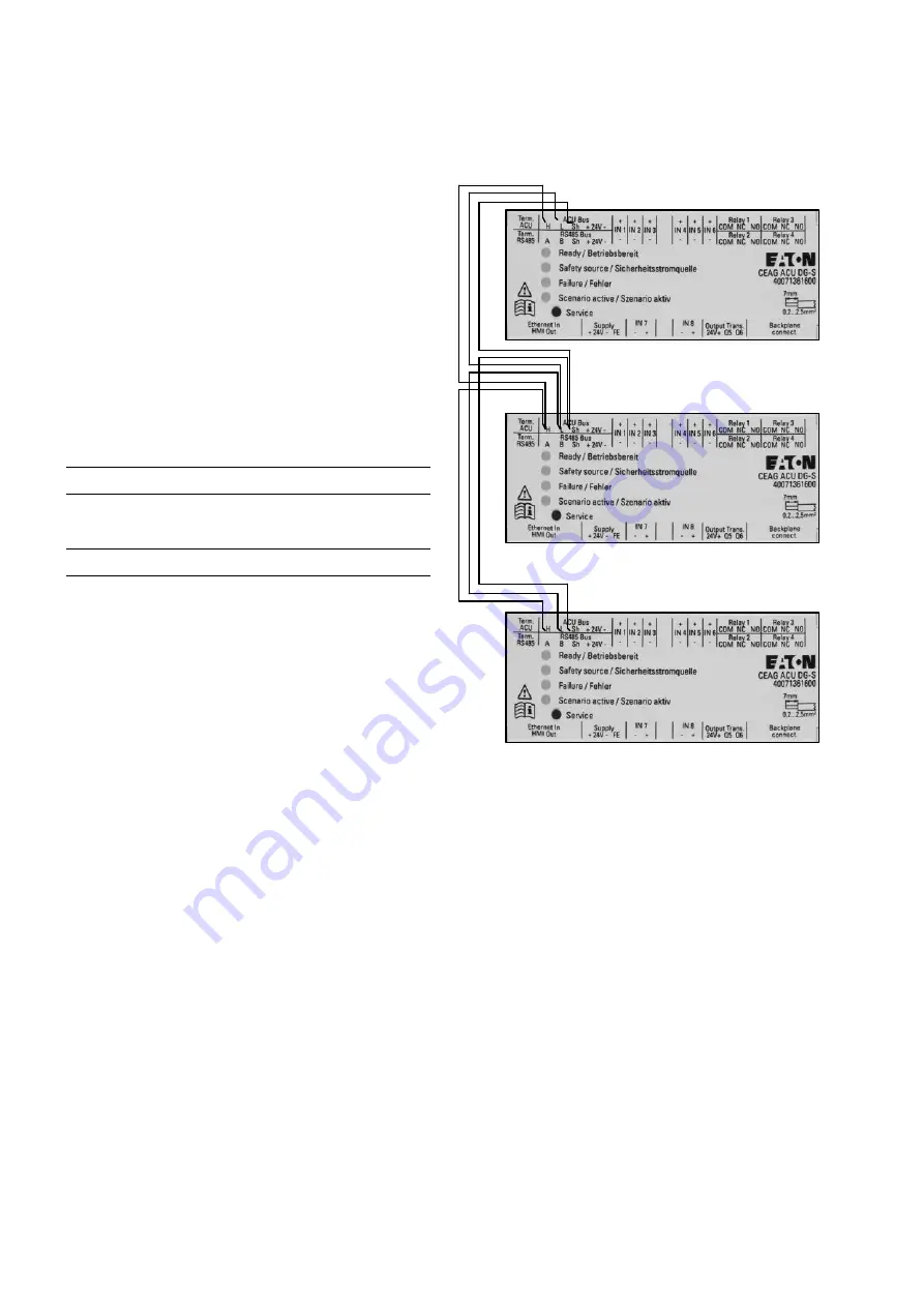
ACU DG Bus sub-station connection
Sub-distributors with their own touch display / ACU DG
which are supplied via a DualGuard-S must be connected
to each other via the ACU DG Bus:
• Power failures at sub-distributors are detected and repor-
ted to the DualGuard-S in order to avoid discharge of the
Batterys.
• Switching commands of the 3-PM-IO and 3-PM-IO-INV
modules can work across devices.
• Networked switching actions and information can be
transmitted.
The cores of the ACU DG bus line must be connected to
the ACU DG terminal strip at the terminal points ACU DG
Bus H, ACU DG Bus L. The ACU DG bus line must be con-
nected to the ACU DG terminal strip at the terminal points
ACU DG Bus H, ACU DG Bus L.
NOTE!
A parallel connection of data lines is not permitted and
does not extend the permissible line length.
ATTENTION!
Bus topology: linear, double terminated (no spur lines per-
mitted). Cable type (minimum requirement): IY(ST)Y 4 x 2
x 0.8 mm (twisted pair, shielded) - the cable shield must be
connected to the SE terminals of each module and must
only be earthed in the DualGuard-S switch cabinet.
Only one pair of wires may be used as data lines within the
shield - it is not permitted to bandle several data lines within
one shielded line!
The 120Ω Ohm terminating resistor is integrated in the
ACU DG modules and can be activated by a DIL switch.
L1
N1
L2
N2
L3
N3
L4
N4
N6
L7
N7
+24V
-1
+24V
-2
+24V
-3
-24V
-1
-24V
-2
-24V
-3
SE-IN
A-IN
B-IN
SE-
O
ut
A-
O
ut
B-
O
ut
B2
B1
L5
N5
L6
L8
N8
PE1
PE2
Adresse
3-PM-IO
H L Sh1 +24.1 -24.1 A B
Sh2 +24.2 -24.2 IN1.1 IN1.2 IN2.1 IN2.2 IN3.1 IN3.2 IN4.1 IN4.2 IN5.1 IN5.2 IN6.1 IN6.2 K1.COM K1.NO K1.NC
K2.COM K2.NO K2.NC K3.COM K3.NO K3.NC K4.COM
K4.NO K4.NC
HMI ETN +24.3 -24.3 IN7.1 IN7.2 IN8.1 IN8.2 K5.COM K5.NO K6.COM K6.NO
ACU
H L A B
L3
L2
N
PE
L1


