6
EATON Char-Lynn
VIS 45 Series Bearingless Motors Parts and Repair Manual C-MOLO-TM006-E March 2008
VIS Bearingless
Motors -
45 Series
Reassembly
9
1
4
7
2
5
8
6
3
Flange Assembly
13.
Position flange on work bench
with the o-ring grooves face
down and install face seal (72,9
[2.87] OD).
14.
With mounting flange o-rings
grooves up, install two o-ring
seals (150,8 [5.94] ID & 107,7
[4.24] ID) into flange. Install back
up-up ring (69,5 [2.74] OD) over
o-ring (63,2 [2.49] ID) with flat
side up (See Figure 3). Back-up
ring and o-rings may be greased to
assist in retaining parts.
Final Assembly
15.
Place drive into build fixture.
Place mounting flange (seal
grooves up) over drive.
16.
Place Belleville spring (concave
side down) in groove in mount-
ing flange.
17.
Place outer and inner balance
plates on mounting flange. Align
shuttle flow cavity of outer bal-
ance plate with shuttle flow cavi-
ty of mounting flange.
18.
Install two steel balls into seats
of star (one per seat). Retain
balls with grease.
19.
Install o-ring seals (150,8 [5.94]
ID) in o-ring grooves on both
sides of Geroler. Seal on balance
ring side of Geroler must have
sufficient coating of petroleum
jelly to assist in retaining seal in
the groove. Place Geroler assem-
bly over outer balance plate.
Make sure that balls are in their
seats. Align shuttle flow cavity of
Geroler with shuttle flow cavity of
outer balance plate.
20.
Place valve plate onto Geroler.
Align bolt holes and shuttle flow
hole with mating holes on
Geroler.
21.
Place end cap on workbench
name plate side down, seal
grooves face up. Install o-rings
(150,8 [5.94] ID & 26,7 [1.05] ID)
into seal grooves. Seals must
have sufficient coating of petro-
leum jelly to assist in retaining
seal in the groove.
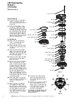
Figure 5
Screw, Torx Head
End Cap
Seal, Square Cut
O-ring
Valve Plate
Seal, Square Cut
Geroler
Check Balls
Drive
Seal, Square Cut
Balance Plate, Outer
Balance Plate, Inner
Seal, Square Cut
Spring, Belleville Disc
Backup ring
O-ring
Flange
Face Seal
O-ring
Seal, Square Cut
O-ring
O-ring
Flange
Balance Plate, Inner
Spring, Belleville Disc
22.
Carefully invert end cap and
place onto valve plate. Make
sure that shuttle flow cavities
are aligned.
23.
Install nine cap screws lubricat-
ed with DTE-26/DTE-24. Pre-
torque each in a crisscross pat-
tern to 80±10 lb-ft. Finally, in a
crisscross pattern, tighten
screws to 135±5 lb-ft].
Note: Damage to the balance plate will
occur if these bearingless motors are
lifted by the drive.
Figure 3
Figure 4


