29
Instruction Booklet
IB 52-01-TE
Effective October 2010
Instructions for the Eaton Type CM52
Network Protectors 800 to 4500 Amperes
EATON COrPOrATION www.eaton.com
29 IB -52-01-TE
Effective 11/05/08 (super cedes 11/19/03) IB 52-01-TE
29
•
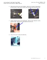
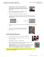
Lift the levering crank access door and insert the end of the
levering crank (3/8 ” square). As the levering crank is turned
counter clockwise, the worker can observe the red window on the
break er moving from the CONNECT position toward the yellow
TEST position.
•
The breaker will
slightly drop down as the breaker disconnects
from the transfo rmer and netwo rk side bus work.
•
If the springs are charg ed, they will discharge when racked out.
•
A full yellow position indicates that the protector is disconnected from the Network and
Transform er side bus. Continue to crank until the cranks stops. The green DISCONNECT
window will appear.
•
Lift up the handle rails on each side of the break er and pull the breaker out until it is completely
fo rward.
•
Using the same crank, insert the 10mm socket and remove the
front cover bolts. Pull slightly down on the charge handle and
remove the cover.
Breaker Mechanical Inspection
•
Inspect the condition of the wiring. Look for fray ed or damaged wire.
•
Remove the Arc Chutes. Look through the arc chutes to make sure the
vents are free and clear.
•
Manually charge the breaker with the charge handle.
•
The Flag will indicate “ Charged” after the closing spring is compressed. Push the
button labeled “PUSH ON”. This will close the breaker.
•
Check the contact wear. A contact wear indicator is a side-by-side ledge that can be
check ed by looking straight down into the arc chamber. With the contacts in good
condition the ledge is covered by the back edge o f the moving contacts. The
contacts or break er should be replaced if the ledge is not completely covered.
NOTE: There are no adjustments needed for contact pressure, no lubrication is required. Do not wipe
away or add any grease or lubricant.
Disconnected
Test


