background image

25

GB

Explosion-protected, light alloy Ex-d (e) control stations and  
distributions, Series: GHG 64

1.2.6  Main current switch actuator unit

Degree of protection to IEC/EN 60529

IP 66

Weight

0.12 kg

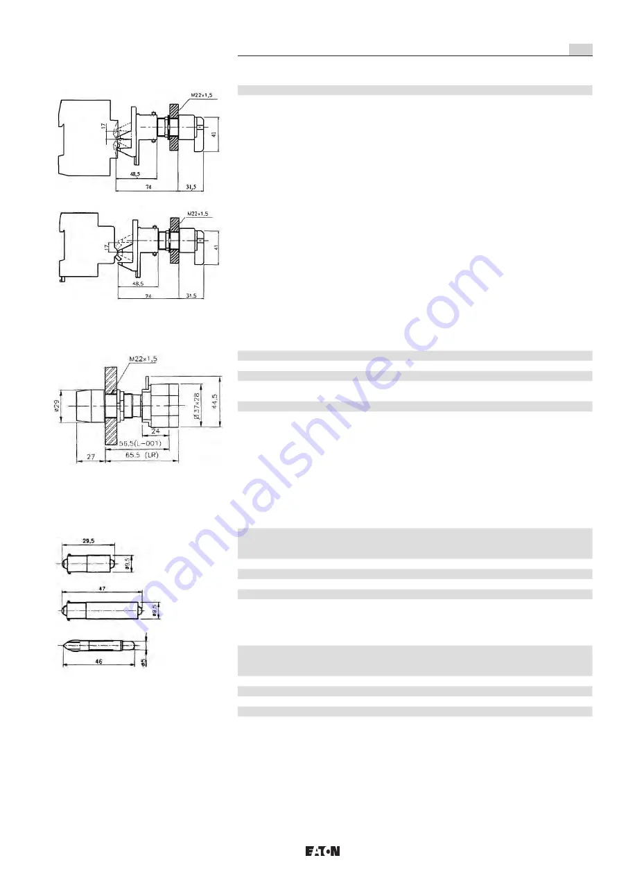
1.2.7  Signal lamp

Degree of protection to IEC/EN 60529

IP 66

Rated voltage LED

12 V - 250 V AC/DC

Rated power

approx. 2.6 W

Permissible ambient temperature

-40° C up to +55° C (catalogue version)

(Special versions permit deviating temperatures.)
Terminals

2 x 2.5 mm²

Weight

approx. 0.066 kg

1.2.8  LED BA 9S

Rated voltage

12 V AC / DC

24 V AC / DC

130 V AC / DC

220 V AC / DC

12 V to 30 V AC / DC

Rated current

approx. 8 m A

Rating

approx. 0.8 W

Permissible ambient temperature

-30° C to +75° C

Beam angle

24°

Holder

BA9S

1.2.9  LED "Teleslide"

Rated voltage

12 V AC / DC

24 V AC / DC

130 V AC / DC

220 V AC / DC

12 V to 30 V AC / DC

Rated current

approx. 8 m A

Rating

approx. 0.8 W

Permissible ambient temperature

-30° C to +75° C

Beam angle

24°

Holder

Teleslide

Signal lamp

LED

LED BA9S 

"long"

LED BA9S 

Standard

LED 

Teleslide

Main current switch actuator unit

Summary of Contents for CROUSE-HINDS Ex - d Series

Page 1: ...uereinheit Verteilung aus Leichtmetall GHG 64 Explosion protected flameproof control station and distributions Ex d e Series GHG 64 Betriebsanleitung Operating instructions Mode d emploi CROUSE HINDS SERIES GHG 640 7004 P0001 D GB d ...

Page 2: ...emmen 30 10 2 Anordnung v Bedienelementen im Gehäuseoberteil 31 10 3 Anhang Verdrahtungstabellen 36 10 4 AnhangTypenschlüssel 41 10 5 NPT Gewinde 42 Konformitätserklärung separat beigelegt Contents Contents 2 1 Technical Data 16 1 1 Ex d aluminium enclosure 16 1 1 1 Permissible power loss Ex d encl 17 1 1 2 Dimensions Ex d enclosure 17 1 1 3 Dimensions Ex e connection box 17 1 2 1 1 Main Safety sw...

Page 3: ...284 630 A 240 mm 9 430 x 650 x 284 630 A 240 mm 10 430 x 650 x 431 800 A 300 mm 11 650 x 650 x 442 1150 A 2 x 300 mm nur II 2G Ex d IIB Zulässige Umgebungstemperaturbereich Größe Umgebungstemperaturbereich 1 5 55 C bis 60 C für Kategorie IIB und IIB H2 6 8 55 C bis 60 C für Kategorie IIB und IIB H2 9 10 20 C bis 60 C für Kategorie IIB und IIB H2 11 20 C bis 60 C für Kategorie IIB gültig für alle G...

Page 4: ...röße AA BB CC 1 215 226 128 2 215 226 128 3 215 226 128 4 325 300 128 5 325 300 254 1 1 2 Abmessungen Ex d Gehäuse Gehäuse Maße in mm Montageplatte Gewicht Größe A B C X Y H I T Kg 1 210 210 191 187 145 140 140 120 8 7 2 210 320 191 185 255 140 250 118 13 0 3 210 320 284 185 255 140 250 211 17 0 4 320 320 191 295 255 250 250 118 17 1 5 320 320 284 295 255 250 250 211 21 7 6 320 430 191 295 365 250...

Page 5: ...essungsspannung 690 V 50 60 Hz Bemessungsstrom 250 A Zulässige Kurzschlussvorsicherung bis UN 400 V bis UN 500 V bis UN 690 V 315 A gG 315 A gG Schaltvermögen AC 23 250 A 250 A 250 A Leitungseinführung gemäß Kundenspezifikation im Rahmen der Zulassung Anschlussklemme M8 x 25 Prüfdrehmoment Anschlussklemme 22 Nm Gewicht 3 polig gem Spezifikation 6 polig gem Spezifikation Maßbild Gehäuse Gr 80 A Maß...

Page 6: ...pezifikation 1 2 1 4 Hilfskontakte Bemessungsspannung 690 V 50 60 Hz Bemessungsstrom 20 A Zulässige Kurzschlussvorsicherung 25 A gL bei 690 V Schaltvermögen AC 23 AC 15 230 V 8 0 A 400 V 6 0 A DC 13 24 V 6 0 A 230 V 0 4A Ausführung mit Goldspitzkontakten max 400 mA Anschlussklemmen 2 x 1 5 4 0 mm Prüfdrehmoment Anschlussklemme 2 5 Nm 1 2 1 5 Eigensichere Schalterstromkreise Sicherheitstechnische M...

Page 7: ...ubtiefe 5 mm 8 mm EN IEC 60079 1 Abs 5 3 Anschlussklemmen siehe Einbaukomponenten Prüfdrehmomente Anschlussklemmen 2 50 Nm 1 2 2 1 Drucktaster Reset Drucktaster Schlagtaster Schlagtaster mit Schlüsselentriegelung Bemessungsspannung bis max 500 V Max Bemessungsstrom 10 A Schaltvermögen AC 15 220 V 10 0 A 380 V 7 5 A 500 V 5 0 A Schaltvermögen DC 13 24 V 2 75 A 60 V 1 10 A 110 V 0 55 A 220 V 0 27 A ...

Page 8: ... 126 kg 2 Kontaktblöcke 4 Kontakte ca 0 154 kg 1 2 2 6 Schlagtaster mit Schlüsselentriegelung Schutzart nach EN IEC 60529 IP 66 Gewicht Pilz d 36 mm 1 Kontaktblock 1 Kontakt ca 0 176 kg Pilz d 36 mm 1 Kontaktblock 2 Kontakte ca 0 186 kg Pilz d 50 mm 2 Kontaktblöcke 4 Kontakte ca 0 214 kg 1 2 2 7 Schlüsseltaster Schutzart nach EN IEC 60529 IP 66 Gewicht 1 Kontaktblock 1 Kontakt ca 0 172 kg 1 Kontak...

Page 9: ... 25 A 5 5 KW 380 V 440 V 7 5 KW 5 A 25 A 11 KW Typ 40 A bei 220 V 240 V 7 5 KW 14 A 32 A 7 5 KW 380 V 440 V 11 KW 6 A 32 A 15 KW Typ 63 A bei 220 V 240 V 11 KW 16 A 40 A 11 KW 380 V 440 V 18 5 KW 7 A 40 A 22 KW Schaltvermögen DC 20 A 32 A 40 A 63 A ohmische Last T 1mS 24 V 20 A 25 A 40 A 63 A 48 V 12A 20 A 32 A 40 A 60 V 4 5A 7 5 A 23 A 27 A 110 V 1 0A 1 5 A 6 5 A induktive Last T 50 mS 24 V 12 A ...

Page 10: ...0 V 7 5 KW 5 A 25 A 11 KW Typ 40 A bei 220 V 240 V 7 5 KW 14 A 32 A 7 5 KW 380 V 440 V 11 KW 6 A 32 A 15 KW Typ 63 A bei 220 V 240 V 11 KW 16 A 40 A 11 KW 380 V 440 V 18 5 KW 7 A 40 A 22 KW Schaltvermögen DC 20 A 32 A 40 A 63 A ohmische Last T 1mS 24 V 20 A 25 A 40 A 63 A 48 V 12A 20 A 32 A 40 A 60 V 4 5A 7 5 A 23 A 27 A 110 V 1 0A 1 5 A 6 5 A induktive Last T 50 mS 24 V 12 A 20 A 32 A 40 A 48 V 2...

Page 11: ... möglich Anschlussklemme 2 x 2 5 mm Gewicht ca 0 066 kg 1 2 8 Leuchtdiode BA 9S Bemessungsspannung 12 V AC DC 24 V AC DC 130 V AC DC 220 V AC DC 12 V bis 30 V AC DC Bemessungsstrom ca 8 m A Lampenleistung ca 0 8W Temperaturbereich 30 C bis 75 C Lichtaustrittswinkel 24 Fassung BA9S 1 2 9 Leuchtdiode Teleslide Bemessungsspannung 12 V AC DC 24 V AC DC 130 V AC DC 220 V AC DC 12 V bis 30 V AC DC Bemes...

Page 12: ...ormaler Industrieatmosphäre gewährleisten Ex d Schutzgehäuse Aluminiumlegierung polyesterbeschichtet Ex e Anschlusskasten Edelstahl Stahlblech lackiert Bei einem Einsatz in extrem aggressiver Atmosphäre können Sie zusätzliche Informa tionen über die Chemikalienbeständigkeit der eingesetzten Materialien bei Ihrer zuständigen Cooper Crouse Hinds Niederlassung erfragen 5 Verwendung Eigenschaften Die ...

Page 13: ...igungsöffnung angepasst sein Die Befestigung mit entsprechenden Haken schrauben oder Befestigungslaschen ist ebenfalls möglich Die Befestigungslaschen können nach oben und unten oder seitlich ausgerichtet montiert werden Zum Anschrauben an die Gehäuse geeignete Schrauben mit Federscheibe und Unterleg scheibe verwenden Zum Befestigen der Ex d Schutzgehäuse alle Befestigungslaschen verwenden Befesti...

Page 14: ...n Bei der Auswahl der KLE ist dasVolumen des Ex d Gehäuse zu beachten Beim Einsatz von KLE mit einer niedrigeren als der für das Gerät zutreffenden IP Schutzart SieheTechnische Daten wird die IP Schutzart des gesamten Gerätes reduziert Die für die eingebauten druckfesten Einführun gen und Verschlussstopfen maßgebenden Montagerichtlinien sind zu beachten Achtung Beim Anziehen der Hutmutter der Meta...

Page 15: ...hlussquerschnitt von max 35 mm erfolgt der Anschluss an einem eingepressten Stehbolzen siehe Fig 4 über Leiter mit entsprechenden Kabelschuh Aderendhülse oder mit starren Leitungen Ab einem Anschlussquerschnitt von 10 mm müssen Kabelschuhe verwendet werden Das Prüfdrehmoment der Anschluss schraube Mutter M8 beträgt 10 Nm Bei einem Anschlussquerschnitt von größer 35 mm wird ein Einschraubgewinde M1...

Page 16: ... Schäden anTeilen der druckfesten Kapselung oder den zünddurchschlagsicheren Spalten sind durch Austausch mit Originalteilen umgehend zu beheben oder vom Gerätehersteller instandsetzen zu lassen Der Explosionsschutz ist sonst nicht mehr gewährleistet Bei erforderlichen Instandsetzungsarbeiten nachfolgenden Abschnitt 8 beachten 8 Reparatur Instandsetzung Instandsetzungsarbeiten Reparaturen die den ...

Page 17: ...A 180 mm 7 320 x 430 x 284 400 A 180 mm 8 430 x 430 x 284 630 A 240 mm 9 430 x 650 x 284 630 A 240 mm 10 430 x 650 x 431 800 A 300 mm 11 650 x 650 x 442 1150 A 2 x 300 mm only II 2G Ex d IIB Permissible ambient temperature Size Ambient temperature range 1 5 55 C to 60 C for category IIB and IIB H2 6 8 55 C to 60 C for category IIB and IIB H2 9 10 20 C to 60 C for category IIB and IIB H2 11 20 C to...

Page 18: ... 215 226 128 2 215 226 128 3 215 226 128 4 325 300 128 5 325 300 254 1 1 2 Dimensions Ex d enclosure Enclosure dimension in mm Mounting plate Weight Size A B C X Y H I T Kg 1 210 210 191 187 145 140 140 120 8 7 2 210 320 191 185 255 140 250 118 13 0 3 210 320 284 185 255 140 250 211 17 0 4 320 320 191 295 255 250 250 118 17 1 5 320 320 284 295 255 250 250 211 21 7 6 320 430 191 295 365 250 360 116...

Page 19: ...ated current 250 A Perm short circuit back up fuse up to UN 400 V up to UN 500 V up to UN 690 V 315 A gG 315 A gG Switching capacity AC 23 250 A 250 A 250 A Cable entries standard version according to customer specifications under the approval Terminals M8 x 25 Test torque terminals 22 Nm Weight 3 pole acc to specification 6 pole acc to specification Dimension drawing Enclosure Gr 80 A Dimension d...

Page 20: ...n 6 pole acc to specification 1 2 1 4 Auxiliary contacts Rated voltage 690 V 50 60 Hz Rated current 20 A Perm short circuit back up fuse 25 A gL bei 690 V Switching capacity AC 23 AC 15 230 V 8 0 A 400 V 6 0 A DC 13 24 V 6 0 A 230 V 0 4A Versions with gold tipped contacts max 400 mA Terminals 2 x 1 5 4 0 mm Test torque terminals 2 5 Nm 1 2 1 5 Intrinsically safe switch circuits Max safe voltage Um...

Page 21: ...omponents Test torques Connection terminals 2 50 Nm 1 2 2 1 Push button Reset Push button Mushroom head push button Mushroom head push button with key released Rated voltage up to max 500 V Max rated current 10 A Switching capacity acc AC 15 220 V 10 0 A 380 V 7 5 A 500 V 5 0 A Switching capacity acc DC 13 24 V 2 75 A 60 V 1 10 A 110 V 0 55 A 220 V 0 27 A Terminals 2 x 2 5mm 1 2 2 2 Push button De...

Page 22: ...cc 0 126 kg 2 contact elements 4 contacts acc 0 154 kg 1 2 2 6 Mushroom head push button with key releases Degree of protection to IEC EN 60529 IP 66 Weight Pilz d 36 mm 1 contact element 1 contact acc 0 178 kg Pilz d 36 mm 1 contact element 2 contacts acc 0 186 kg Pilz d 50 mm 2 contact elements 4 contacts acc 0 214 kg 1 2 2 7 Key switch Degree of protection to IEC EN 60529 IP 66 Weight 1 contact...

Page 23: ... 4 0 KW 8 A 25 A 5 5 KW 380 V 440 V 7 5 KW 5 A 25 A 11 KW Type 40 A at 220 V 240 V 7 5 KW 14 A 32 A 7 5 KW 380 V 440 V 11 KW 6 A 32 A 15 KW Type 63 A at 220 V 240 V 11 KW 16 A 40 A 11 KW 380 V 440 V 18 5 KW 7 A 40 A 22 KW Switching capacity DC 20 A 32 A 40 A 63 A Resistive loads T 1mS 24 V 20 A 25 A 40 A 63 A 48 V 12A 20 A 32 A 40 A 60 V 4 5A 7 5 A 23 A 27 A 110 V 1 0A 1 5 A 6 5 A Inductive loads ...

Page 24: ...5 KW 380 V 440 V 7 5 KW 5 A 25 A 11 KW Type 40 A at 220 V 240 V 7 5 KW 14 A 32 A 7 5 KW 380 V 440 V 11 KW 6 A 32 A 15 KW Type 63 A at 220 V 240 V 11 KW 16 A 40 A 11 KW 380 V 440 V 18 5 KW 7 A 40 A 22 KW Switching capacity DC 20 A 32 A 40 A 63 A resistive load T 1mS 24 V 20 A 25 A 40 A 63 A 48 V 12A 20 A 32 A 40 A 60 V 4 5A 7 5 A 23 A 27 A 110 V 1 0A 1 5 A 6 5 A inductive load T 50 mS 24 V 12 A 20 ...

Page 25: ...mit deviating temperatures Terminals 2 x 2 5 mm Weight approx 0 066 kg 1 2 8 LED BA 9S Rated voltage 12 V AC DC 24 V AC DC 130 V AC DC 220 V AC DC 12 V to 30 V AC DC Rated current approx 8 m A Rating approx 0 8W Permissible ambient temperature 30 C to 75 C Beam angle 24 Holder BA9S 1 2 9 LED Teleslide Rated voltage 12 V AC DC 24 V AC DC 130 V AC DC 220 V AC DC 12 V to 30 V AC DC Rated current appr...

Page 26: ...here Ex d enclosure aluminium alloy with polyester coating Ex e terminal box stainless steel sheet steel painted Additional information on the resistance of the materials used to chemical substances when used in extremely aggressive atmos pheres can be obtained from your branch of Cooper Crouse Hinds 5 Use Properties The Ex d control stations and distributions are used within the limitations of th...

Page 27: ...frames they shall rest evenly without twisting on the fastening points provided for this purpose The screws and washers selected shall match the fixing holes The flameproof enclosure can also be mounted using hook bolts or with mounting brackets The mounting brackets can be fitted facing upwards downwards or sideways Suitable screws with a spring washer and washer shall be used for screwing them o...

Page 28: ...onsideration When using cable entries with a degree of protection that is lower than the IP protection of the apparatus seeTechnical Data the degree of IP protection for the complete unit is reduced The relevant mounting directives for flameproof cables entries and blanking plugs shall be observed Attention When tightening the cap nut of the metal cable entries a suitable tool shall be used to sto...

Page 29: ...r to take suitable protective measures Connection for potential equalization on the enclosure wall In the case of terminal cross sections up to 35 mm connection is made at the stud see Fig 4 using a conductor with suitable cable lug ferrule or rigid wires Cable lugs must be used for terminal cross sections greater than 10 mm2 The test torque for the terminal screw M8 nut is 10 Nm If the terminal c...

Page 30: ... 94 Renolit Unitemp 2 Damages to any parts of the flameproof encapsulation or flameproof joints shall be remedied immediately using original parts or the damaged parts shall be repaired by the manufacturer Otherwise the explosion protection is no longer guaranteed If in the course of servicing it is ascertained that repairs are necessary section 8 of these operating instructions shall be observed ...

Page 31: ...19 14 14 11 9 9 7 x z 2 92 92 76 58 46 38 14 x z 3 138 138 114 87 69 57 w y 1 67 67 56 42 34 28 21 21 17 w y 2 184 184 152 116 92 76 28 8 x z w y 1 67 67 56 42 34 28 21 21 17 13 13 11 x z w y 2 134 134 112 84 68 56 42 x z w y 3 201 201 168 126 102 84 9 x z 1 67 67 56 42 34 28 21 21 17 13 13 11 11 9 9 x z 2 134 134 112 84 68 56 42 42 34 26 x z 3 246 246 206 154 124 102 78 78 w y 1 110 110 92 69 56 ...

Page 32: ...hbuttons and lamps Raster für Schaltervorsätze 20 A Distance between centres for switch elements 20 A Raster 1 2 3 oder A B C für Vorsätze Distance 1 2 3 or A B C for actuator elements Bereich nur für Befehlsgeber Leuchtmelder Drilling area for pushbuttons and signal lamps only 32 A Schalter 32 A switch 2 poliger Fi 2 pole RCB 40 A Schalter 63 A Schalter 40 A switch 63 A switch 20 A Schalter 20 A ...

Page 33: ...0 172 75 105 60 82 M22 x 1 5 160 160 75 172 M22 x 1 5 202 60 1 poliger Automat 2 poliger Automat 3 poliger Automat 4 poliger Automat 1 pole MCB 2 pole MCB 3 pole MCB 4 pole MCB 40 A Schalter 63 A Schalter 40 A switch 63 A switch 2 poliger Fi 4 poliger Fi 2 pole RCB 4 pole RCB Taster Leuchten Schalter Pushbuttons signal lamps Switches 32 A Schalter 32 A switch 2poliger Fi 4poliger Fi 1poliger Autom...

Page 34: ...ignal lamps switches MCBs RCBs in Ex d enclosures 320 430 430 430 430 650 650 650 UK 16 UK 35 75 60 150 60 150 120 150 60 120 Taster Leuchten 20A Schalter 32 A Schalter 40 A Schalter 63 A Schalter Abstand 60 mm zwischen 1 poligen 1 2 poligen 1 3 poligen 1 4 poligen 2 poligen 2 3 poligen 2 4 poligen Automaten Pushbuttons Signal lamps 20A switches 32 A switch 40 A switch 63 A switch Distance 60 mm b...

Page 35: ... 320 430 Drilling surface enclosure cover Size 6 320 430 M22 x 1 5 15 11 16 2 3 14 13 12 7 8 9 10 6 5 4 1 A B C D E F G H I J K L 215 75 160 60 202 247 5 4 3 2 7 8 9 10 11 12 18 17 16 15 14 13 19 20 21 22 23 24 6 1 A B C D E F G H I J K L M N O P Q R S T 215 215 75 247 M22 x 1 5 60 322 10 2 7 Fläche für Bedienelemente Größe 8 430 430 Drilling surface enclosure cover Size 8 430 430 ...

Page 36: ... 27 26 25 33 34 35 36 37 38 39 40 48 56 55 47 46 54 45 53 44 52 43 51 50 42 41 49 32 A B C D E F G H I J K L M N O P Q R S T U V W X Y Z AA AB AC AD AF AG AH AI AJ AK AL AM AN AO AP AQ AR AS AT AU AV AW AX 325 325 75 472 M22 x 1 5 472 60 10 2 Anordnung von Bedienelementen im Gehäuseoberteil Arrangement of actuators in enclosure cover 10 2 8 Fläche für Bedienelemente Größe 9 430 650 Drilling surfac...

Page 37: ... 35 50 3 6 1 10 114 16 39 76 296 20 14 44 86 25 21 48 93 35 14 36 91 50 5 29 75 63 10 35 124 3 80 13 39 139 100 16 36 125 2 15 37 Größe Size 2 210 x 320 x 191 I A Ø in mm 1 5 2 5 4 6 10 16 25 35 50 3 6 1 10 88 16 30 58 228 20 12 34 66 25 16 37 72 35 11 28 70 50 4 23 58 63 7 27 96 80 10 30 107 100 13 28 3 125 2 11 28 160 10 200 Größe Size 4 320 x 320 x 191 I A Ø in mm 1 5 2 5 4 6 10 16 25 35 50 3 6...

Page 38: ... 35 13 33 83 50 5 27 69 63 9 32 114 3 80 12 35 128 100 15 33 125 2 13 34 160 11 30 200 10 26 80 225 4 15 31 250 8 19 315 4 400 500 No 138 138 114 87 69 57 28 21 17 9 9 7 Verdrahtungstabellen Annex wiring tables Größe Size 5 320 x 320 x 284 I A Ø in mm 1 5 2 5 4 6 10 16 25 35 50 3 6 1 10 126 16 43 84 327 20 18 49 95 25 23 54 103 35 15 40 100 50 6 33 83 63 11 38 137 3 80 15 43 153 100 18 40 125 2 2 ...

Page 39: ... 19 42 125 2 2 17 43 160 14 32 200 13 32 100 225 5 18 39 250 10 24 315 5 400 500 No 139 139 116 87 69 57 28 21 17 9 9 7 Verdrahtungstabellen Annex wiring tables Größe Size 8 430 x 430 x 284 I A Ø in mm 1 5 2 5 4 6 10 16 25 35 50 70 95 120 150 3 6 1 10 142 16 49 94 367 20 20 55 106 25 26 60 116 35 17 45 113 50 6 37 93 63 12 43 154 3 80 16 48 172 100 20 45 125 2 2 18 46 160 16 40 200 14 35 108 225 5...

Page 40: ... 43 200 15 37 115 225 6 21 45 250 11 27 57 315 5 16 34 400 7 23 500 3 No 246 246 206 154 124 102 78 78 34 26 26 11 11 9 9 Verdrahtungstabellen Annex wiring tables Größe Size 10 430 x 650 x 437 I A Ø in mm 1 5 2 5 4 6 10 16 25 35 50 70 95 120 150 185 240 3 6 1 10 194 16 67 129 502 20 27 75 146 25 36 82 159 35 24 62 154 50 9 50 128 63 17 59 211 3 80 23 66 236 100 28 62 125 2 3 25 63 160 22 55 200 20...

Page 41: ... 5 No 270 270 226 169 134 114 85 85 68 44 44 18 18 15 15 Beispiel für die Anzahl der verwendeten Leiter 1 Leiter von außen 1 5 mm 2 Interner Verbindungsleiter 1 5 mm 3 Interner Verbindungsleiter 1 5 mm 4 Interner Verbindungsleiter 1 5 mm 5 Leiter nach außen 1 5 mm für die Berechnung müssen 5 Leiter berücksichtigt werden for calculation based on 5 conductors Example of the number of conductors used...

Page 42: ...rachten und erfordern in vielen Fällen eine Messung Erwärmungsnachweis Note 1 max number of terminals depending on the above mentioned apparatus type and the built in 2 wire terminals 2 max number of terminals depending on the above mentioned apparatus type and the max number of conductors 3 max number of conductors depending on the cross section and allowed continuous current for the mentioned ap...

Page 43: ...210x210 side 210x320 side 210x320 high side 320x320 side 320x320 high side 320x430 side 320x430 high side 430x430 side 430x650 side 430x650 high side 650x650 Seite w y 11mm x z 11mm w y 12mm x z 12mm w y 12mm x z 12mm w y 12mm x z 12mm w y 12mm x z 12mm w y 12mm x z 12mm w y 12mm x z 12mm w y 14 5mm x z 14 5mm w y 14 5mm x z 16 5mm w y 16 5mm x z 16 5mm w y 16 5mm x z 16 5mm 1 2 11 7 6 48 x x x x ...

Page 44: ...e la Union Europea EST Seda kasutusjuhendit oma riigikeeles võite küsida oma riigis asuvast asjaomasest Cooper Crouse Hindsi CEAG esindusest FIN Tarvittaessa tämän käyttöohjeen käännös on saatavissa toisella EU n kielellä Teidän Cooper Crouse Hinds CEAG edustajaltanne GR Cooper Crouse Hinds CEAG H A kezelési útmutatót az adott ország nyelvén a Cooper Crouse Hinds CEAG cég helyi képviseletén igénye...

Reviews: