12
6.2 Opening the device /
Electrical connection
Before opening flameproof enclosures with
or without switches, it is necessary to ensure
that there is no voltage or to take suitable
protective measures.
The connection of explosion-protected
flameproof enclosures and distributions may
only be carried out by specialists.
If flameproof apparatus without connection or bus
bar boxes in the type of protection ”Increased
Safety” are to be connected, this flameproof
apparatus is connected directly in the flameproof
enclosure using certified flameproof cable entries,
whereby the mounting instructions for the cable
entry shall be taken into account (see Section
6.3.2 Cable Entries).
Fig. 3
1
2
3
Fig. 4
1
2
4
3
6.1 Mounting
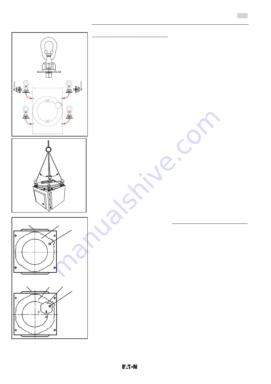
The flameproof enclosure can lift with a minimum
of two swivel eye bolts.
They can fix at the fixing points as shown in Fig. 1,
Fig. 2 and dimension drawings. The swivel eye
bolts have to be suitable for this use and for the
weight of the flameproof enclosure.
The swivel eye bolts chosen shall fit the fixing
points
Ø 14 for enclosures sizes 1, 2, 4, 5 and 7
Ø 23 for enclosures size 6.
Use big size washers to protect the flameproof
enclose against damage. Especially if the
flameproof enclosure are use for wall mounting
and the swivel eye bolts have to angled square.
Use nuts to fix the swivel eye bolts. Observe the
instruction of the swivel eye bolts.
In addition to the notes of the manufacturer, the
relevant national regulations and guidelines for
lifting loads have to be observed.
When the flameproof enclosures and
distributions are mounted directly onto the
wall or onto wall or floor frames, they shall
rest evenly only on the fastening points
provided for this purpose.
In order to be able to open the covers of
flameproof enclosures faultlessly, it is
absolutely essential to ensure that the
flameproof enclosures are assembled without
twisting (see technical data for test torques).
Fixing dimensions are shown in the dimension
drawings on pages 9 and 10.
The screws chosen shall fit the fixing hole
M12 for enclosures sizes 1,2,4,5 and 7
M20 for enclosures size 6
and shall not damage the hole (e.g. use of a
washer).
The number of screws used for fixing the
apparatus shall correspond to the number of fixing
holes in the enclosures.
In the event of distributions with several
enclosures in the same size, the covers of the
flameproof enclosures shall not be inter-
changed.
Which flameproof enclosure cover belongs to
which enclosure base can be determined by
identical production numbers on the inside of the
enclosure cover and the front of the enclosure
base.
If distributions that are mounted on a wall or floor
frame are to be divided for transport purposes or
because the maximum distribution length has
been exceeded, the parts of the distribution shall
be reassembled as follows:
Explosion-protected flameproof enclosures and distributions,
series: GHG 6.. and EXKO
1. Place the system units next to each other in
such a way that the fixing points of the bus
bar boxes and the fixing points of the frame
coincide.
2. All the seals between bus bar boxes and/or
also connection boxes shall be inserted
correctly. The parts can then be screwed
together using the screws provided.
3. After this, the electrical connections of the bus
bar systems or the connection terminals of the
connection boxes shall be made correctly at
the points where the system was divided
using the connection pieces provided (copper
rails or wire connectors), whereby the
connections shall be tightened down securely
(see also Section 6.1 ”Electrical connection”).
Special attention shall be paid to the PE
connections.
Separate documents containing assembly
instructions for units in special designs are
provided with the installation.
Warning: Immediately after installation or
erection, distributions on floor frames shall
be safeguarded against falling over.
If necessary, individual system units with a
maximum length of 6.00 m can be built and joined
together at given points to form a distribution
installation.
Warning: The unit assembled via the bus bar
systems shall not exceed the overall length of
6.00 m.
435
430
329
155,5
X
365
14
975
X 405
311
Fig. 1
Fig. 2
< 45°
< 45°
GB


