background image

10

6 Installation

For the mounting and operation, the 

respective national regulations as well as  

the general rules of engineering shall be 

observed (IEC/EN 60079-14).

X

ATEX - IEC

 When mounting the separately certified 

terminals, the clearance an creepage distance 

must be observed in accordance to table 1 of 

IEC/EN 60079-7.

6.1 Mounting

The plastic boxes can be mounted without 
opening their enclosure.

When mounting the terminal boxes directly 
onto the wall, they shall rest evenly only on the 
fastening points provided for them. The chosen 
screw must match the fastening hole (see 
dimensional  drawings page 8) and they shall 
not damage the hole (e.g. use of a washer).

The terminal boxes must be fastened diagonally 
by means of at least 2 screws.

 If the  screws are overtightened, the 

plastic terminal boxes may be damaged.

The plastic terminal boxes GHG 721 0 and  
GHG 721 0 are suitable for fastening onto CCH/
EATON apparatus holders by means  
of self-cutting screws and clip-on mounting 
(see fig. 4 - 7,  page 11 + 12).

 The respective mounting instructions 

will have to be observed.

6.2   Opening the apparatus/ 

Electrical connection

a

 The electrical connection of the 

apparatus may only be carried out by 
skilled staff (IEC/EN 60079-14).


The minimum clearances and creepage  

distances in accordance with IEC/EN 60079-7, 
Table 1, shall be observed.

The table indicating the current load values 
which is provided on the cover inside of the 
terminal boxes is to be observed.

In order to maintain the mode of protection, the 
conductors will have to be connected with 
special care.

 The insulation shall reach up to the 

terminal. The conductor itself shall not  
be damaged.

The connectable min. and max. conductor 
cross-sections will have to be observed. 

All screws and/or nuts of the supply terminals, 
and unused terminals, shall be tightened down.

The fitted standard terminals are designed for 
direct connection of conductors with copper 
cores.

If stud terminals are fitted, DIN cable lugs shall 
be used.


The cable lugs should be crimped onto 

the cable in a workmanlike manner. It is to 
be ensured that the required min. air gaps 
are kept (at 690V ->12mm).

When combining Ex-e/Ex-i it is essential to 
maintain the separation, air and creepage 
distances. The Ex-i circuit wires are to be laid 
separately from the Ex-e circuit wires  
(see e.g. EN/IEC 60079-11).

The connection wires of the Ex-i circuits are 
to be marked (e.g. by colour, light blue).

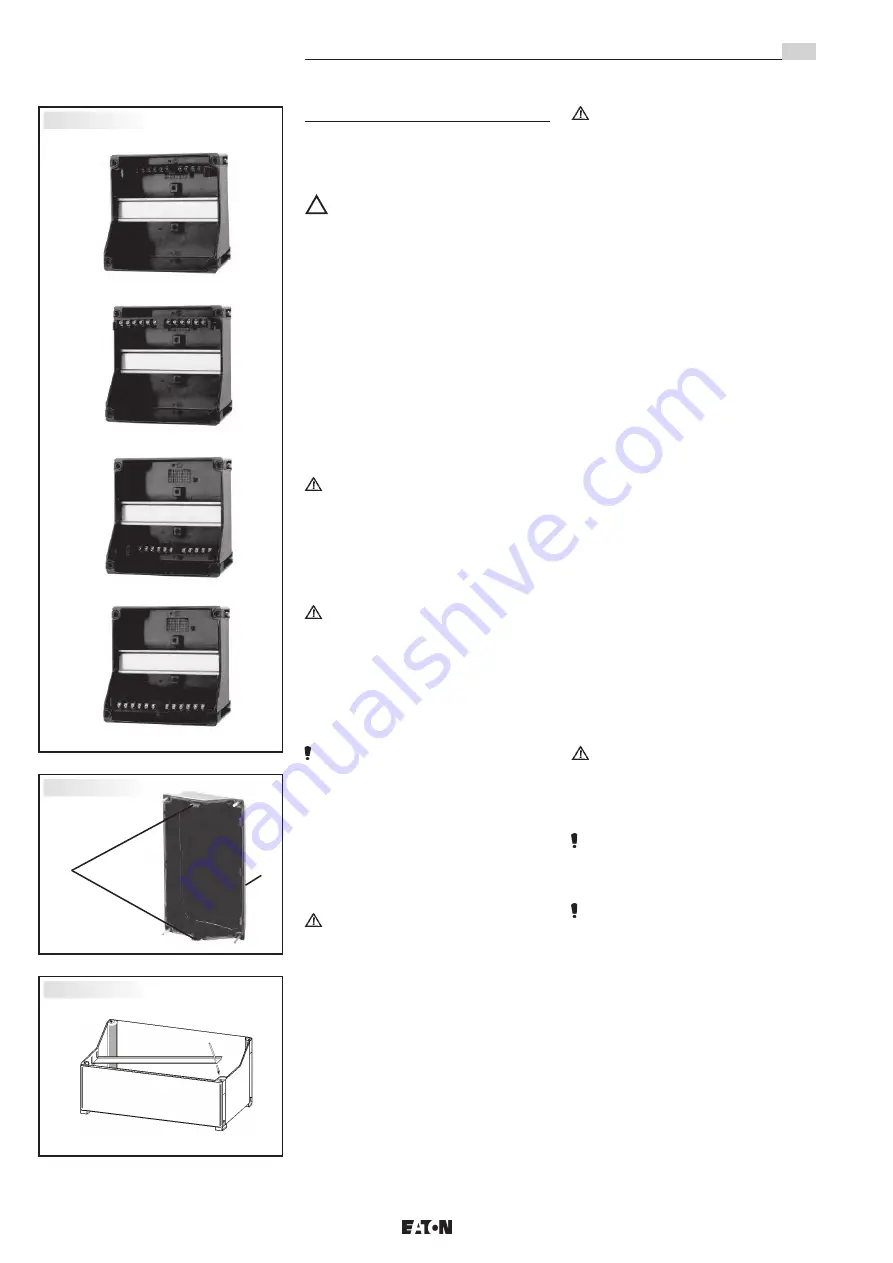
After removing the terminal rail (in order to 
facilitate the entry of cables), the terminal rail 
shall again be properly put in place before 
establishing the electrical connection.

Removal and mounting of the terminal rail are 
performed as follows:

By pressing apart the enclosure sides, the 
terminal rail can be detached from the bottom 
part of the enclosure. 

In order to install the terminal rail, it is fitted 
onto the catch on one side of the enclosure wall 
and then snapped in on the opposite enclosure 
wall (see fig. 3).

The PE rail can optionally be fitted in 4 positions 
(see fig.1):

A Enclosure top side 

- PE-connection bottom

B Enclosure top side 

- PE-connection top

C Enclosure bottom side  - PE-connection bottom

D Enclosure bottom side  - PE-connection top

The PE rail is fitted as follows: It has to be 
pushed home in the respective guide rails that 
are integrated into the lateral enclosure walls.

 The rail must engage into the receptacle 

on the bottom of the housing. Care has to 
be taken that the PE rail has such a position 
that a proper conductor connection is 
ensured.


In the case of building up the electrical 

equipment in the "protective insulation" version, 
appropriate sticker GHG 905 1002 P0005 can 
be requested by the manufacturer.


If the inserted terminal rail is not equipped 

completely with line-up terminals, the terminal 
rail must be included in the equipotential earth 
connection also.

Fig. 1

Fig. 2

Fig. 3

A

B

C

D

1

2

Explosion protected terminal boxes type, GHG 72.

GB

Summary of Contents for Crouse-Hinds GHG 72 Series

Page 1: ...ststoff GHG 72 Explosion protected terminal boxes made of plastic GHG 72 Boites de jonction GHG 72 en plastique pour atmosph res explosives GHG 720 7001 P0001 D GB F o CROUSE HINDS SERIES Betriebsanle...

Page 2: ...3 Conformity with standards 9 4 Field of application 9 5 Use Properties 9 6 Installation 10 7 Maintenance Servicing 11 8 Repairs Overhaul Modifications 12 9 Disposal Recycling 12 10 Current load value...

Page 3: ...temperatur T6 40 C T6 50 C T5 40 C T5 55 C Kunststoffausf hrung GHG 721 0 16W 10W 22W 16W Kunststoffausf hrung GHG 721 1 24W 15W 33W 24W Bemessungsspannung bis 690 V Bemessungsstrom sieheTabelle im Ge...

Page 4: ...g beziehen sich immer auf die aktuelle Version Zus tzliche Erg nzungen z B Jahreszahlangaben sind zu beachten 4 Verwendungsbereich Die Kunststoffk sten sind zum Einsatz in explosionsgef hrdeten Bereic...

Page 5: ...nd DIN Kabelschuhe zu verwenden Das Aufpressen der Kabel schuhe auf das Kabel ist fachgem durchzuf hren Es ist sicherzustellen dass die erforderlichen Mindestluftstrecken eingehalten werden bei 690V 1...

Page 6: ...itz und die Unversehrtheit der Dichtung zu achten Von au en herangef hrte PE Leitungen sind auf die daf r vorgesehene PE Klemme am Flansch anzuschlie en Der maximale Anschlussquerschnitt betr gt 50 mm...

Page 7: ...TON oder einer qualifizierten Elektrofachkraft in bereinstimmung mit national geltenden Regeln durchgef hrt werden EN IEC 60079 19 Umbauten oder nderungen am Betriebs mittel sind nicht gestattet ausge...

Page 8: ...ntrinsic Safety i Max Power dissipation Temperature class Max ambient temperature T6 40 C T6 50 C T5 40 C T5 55 C Plastic version GHG 721 0 16W 10W 22W 16W Plastic version GHG 721 1 24W 15W 33W 24W Ra...

Page 9: ...arately References to standards and directives in these operating instructions always relate to the latest version Other additions e g details relating to the year shall be observed 4 Field of applica...

Page 10: ...inals are designed for direct connection of conductors with copper cores If stud terminals are fitted DIN cable lugs shall be used The cable lugs should be crimped onto the cable in a workmanlike mann...

Page 11: ...sealing element PE conductors fed from outside are to be connected to the PE terminal provided on the flange The maximum cross section is 50mm Attention Metal flanges metal plates and metal cable gla...

Page 12: ...electrician in compli ance with the applicable national rules IEC EN 60079 19 Modifications to the apparatus or changes of its design are not permitted except for the mounting of additional cable entr...

Page 13: ...tion thermique max Classe de temp rature max temp rature ambiante admissible T6 40 C T6 50 C T5 40 C T5 55 C Version GRP GHG 721 0 16W 10W 22W 16W Version GRP GHG 721 1 24W 15W 33W 24W Tension nominal...

Page 14: ...la d claration de conformit jointe s par ment Les r f rences aux normes et directives dans cette notice se r f rent toujours la derni re version Les suppl ments ventuels doivent galement tre respect...

Page 15: ...n aussi celles des bornes non utilis es doivent tre serr es fond La borne standard install e est pr vue pour le raccordement direct des conducteurs au cuivre En cas de bornes tige il faut utiliser des...

Page 16: ...de maintien Les plaques amovibles des boites en acier inoxydable sont mont es de telle facon que l indice de protection IP soit respect Il faut galement veiller au bon logement du joint d tanch it Les...

Page 17: ...sion ne devront tre ex cut es que par CCH EATON ou par un lectricien qualifi en conformit avec la r glementation nationale en vigueur CEI EN 60079 19 Il n est pas permis de transformer ou de modifier...

Page 18: ...18 10 Strombelastungstabelle 10 Current load values 10 Tableau de charge...

Page 19: ...tions Example When using this table the simultaneous factor or the rated load factor in accordance with IEC EN 60439 may be taken into considera tion The table values are given for an ambient temperat...

Page 20: ...55 70 7 14 0 3 0 17 0 4 0 17 5 1 5 21 0 1 3 5 0 gr n green vert M40x1 5 55 70 7 19 0 3 3 22 0 5 5 22 0 3 3 28 0 6 7 7 5 gr n green vert M50x1 5 55 70 7 24 0 6 0 28 0 7 0 28 0 5 0 35 0 7 0 7 5 gr n gre...

Reviews: