background image

8

Empty enclosures GHG 716; industrial

GB

1 Technical 

data

1.1 Enclosure

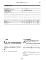
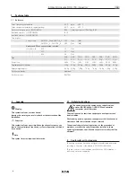
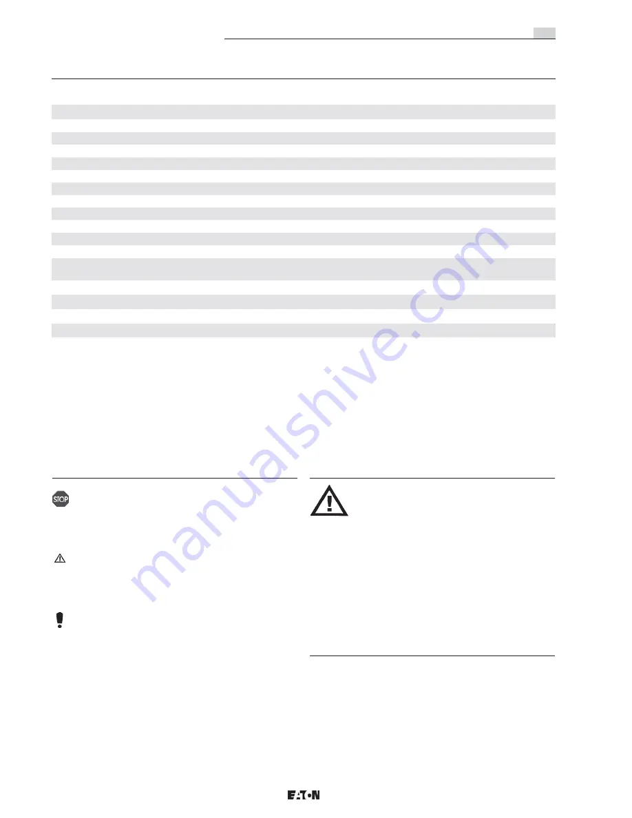
Perm. Operating temperature:

-55° C 

up to

+95° C 

Perm. storage temperature in original packing:

 -55° C 

up to

+55° C 

Protection category acc. to IEC/EN 60529:

IP66

(catalogue version), IP68 (2m); IP69

Insulation class acc. to IEC/EN 62262:

IK 10

Insulation class acc. to IEC/EN 61140:

II

Test torques:

Cover screws:

GHG 716 _1 and GHG 716 _2

1.50

Nm

(M4)

GHG 716 _3 ... GHG 716 _8

3.00

Nm

(M6)

Screws and PE connection inside / outside

for screw size

M4

1.5

Nm

M5

2.5

Nm

M6

3.0

Nm

Type:

GHG 
71_1...

GHG 
71_2...

GHG 
71_3...

GHG 
71_4...

GHG 
71_5...

GHG 
71_6...

GHG 
71_7...

GHG 
71_8...

Power  loss:

3,8 W

7,7 W

13 W

21 W

25 W

46 W

54 W

96 W

Tragfähigkeit der Gehäuse:

25 Kg

25 Kg

50 Kg

50 Kg

50 Kg

50 Kg

50 Kg

50 Kg

Empty weight approx.:

0,3 Kg

0,5 Kg

1,0 Kg

1,5 kg

1,8 kg

3,4 Kg

3,8 Kg

6,2 Kg

Enclosure material:

Aluminum

Enclosure colour:

RAL 7032

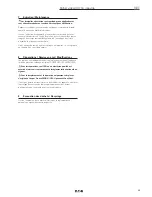
2 Legende

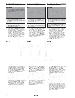
 Warning: 

This symbol indicates a serious hazard.  
Ignoring this warning can result in death or the destruction of the 
installation.


  Attention: 

This symbol indicates a possible failure. Ignoring this warning can 
lead to the total failure of the device, system or operation to which it 
is connected.  

    Note:

This symbol stresses important information.

2.1   Safety instructions

The operations must be carried out by suitably trained 

persons (EN/IEC 60204-1 (VDE 0113)) and specialist 

companies with QM-system.

They shall be used for their intended purpose and in perfect and 
clean condition.

Prior to being put into operation, the apparatus shall be checked in 
accordance with the instructions as per section 6.

The national safety rules and regulations for the prevention of 
accidents, as well as the safety instructions included in these 
operating instructions, that, like this text, are set in italics, shall be 
observed!

Conformity with standards

The empty enclosures have been designed, manufactured and tested 
according to the state of the art and to DIN EN ISO 9001:2008.

They are conform to the standards specified in the EC-Declaration of 
conformity, enclosed separately.

Summary of Contents for Crouse-hinds series

Page 1: ...CROUSE HINDS SERIES Leergeh use GHG 716 Industrie Enclosures GHG 716 industrial Bo tier vide GHG 716 industrie Betriebsanleitung Operating instructions Mode d emploi GHG 710 7001 P0007 D GB F...

Page 2: ...arately D claration de conformit jointe s par ment 1 Technical data 8 2 Legende 8 2 1 Safety instructions 8 3 Conformity with standards 8 4 Field of application 9 5 Application Properties 9 6 Installa...

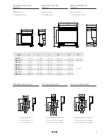
Page 3: ...569 mm 283 mm 110 mm 550 mm 230 mm C Dimensions in mm X xing dimensions Dimensions en mm X dimensions de xation Leergeh use GHG 716 Industrie Enclosures GHG 716 industrial Bo tier vide GHG 716 industr...

Page 4: ...fahr DieseWarnung nicht zu beobachten kann Tod oder die Zerst rung von Einrichtungen zur Folge haben Achtung Dieses Symbol warnt von einem m glichen Ausfall Wird diese Warnung nicht beobachtet kann de...

Page 5: ...ten liegt allein beim Betreiber 6 Installation F r das Errichten Betreiben sind die relevanten nationalen Vorschriften z B BetriSiV Ger tesicherheitsgesetz f r Deutschland sowie die allgemein anerkann...

Page 6: ...Schlie en von Geh usen ohne Deckelscharnier Geh usedeckel auf dem Unterteil ausrichten Die Geh useschrauben anschrauben und diagonal anziehen Pr fdrehmoment sieheTechnische Daten 6 4 2 Schlie en von...

Page 7: ...ng von COOPER CROUSE HINDS CEAG Originalersatzteilen vorgenommen werden Reparaturen d rfen nur von CCH oder einer quali zierten Fachkraft in bereinstimmung mit national geltenden Regeln durchgef hrt w...

Page 8: ...gnoring this warning can result in death or the destruction of the installation Attention This symbol indicates a possible failure Ignoring this warning can lead to the total failure of the device sys...

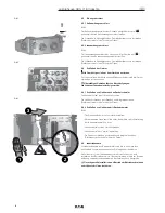
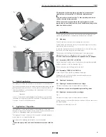
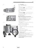
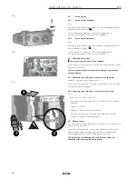
Page 9: ...lded on xing lugs Alternatively the enclosures can be mounted using xing lugs that are available separately 6 2 Opening of enclosures 6 2 1 Opening of enclosures without cover hinges Unscrew cover xin...

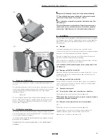
Page 10: ...on category 6 4 1 Closing of enclosure without cover hinges Align the cover with the base Screw in the enclosure screws and tighten them diagonally test torque see technical data 6 4 2 Closing of encl...

Page 11: ...s may only be carried out by COOPER CROUSE HINDS or a quali ed electrician Competent person in compliance with the applicable national rules For replacement and repair only original parts from COOPER...

Page 12: ...ve Cet avertissement peut pas observer la mort ou la destruction des installations ont abouti Attention Ce symbole met en garde contre un ventuel chec Si cet avertisse ment est pas observ l chec total...

Page 13: ...boitier en utilisant les points de xation pr vus en standard En option vous pouvez utiliser les accessoires de xation vendus s par ment Ne jamais percer le boitier 6 2 Ouverture du dispositif 6 2 1 Ou...

Page 14: ...4 1 Fermeture des boitiers avec couvercles sans charni res Aligner le couvercle avec le fond du boitier Vissez les vis du couvercle et serrez les en diagonale couple de serrage voir caract ristiques...

Page 15: ...se reportera au chapitre 8 de ce mode d emploi 8 R parations Remise en tat Modi cations Les remises en tat r parations doivent exclusivement tre effectu es l aide de pi ces de rechange d origine COOP...

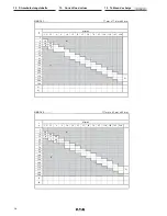
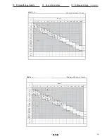
Page 16: ...35 50 70 95 120 150 185 240 3 6 12 4 10 10 12 16 4 11 20 5 25 35 50 63 80 100 125 5 160 200 225 250 3 315 400 500 1 2 GHG712 2 111 mm x 83 mm x 60 mm I A mm 1 5 2 5 4 6 10 16 25 35 50 70 95 120 150 1...

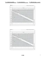
Page 17: ...0 150 185 240 3 6 41 4 10 14 27 16 5 16 30 20 7 17 33 25 5 13 35 50 63 80 100 125 5 160 200 225 250 3 315 400 500 1 2 GHG712 4 223 mm x 128 mm x 80 mm I A mm 1 5 2 5 4 6 10 16 25 35 50 70 95 120 150 1...

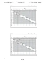
Page 18: ...18 35 16 7 20 39 20 9 22 43 25 6 17 42 35 2 13 35 50 4 16 63 6 80 100 125 5 160 200 225 250 3 315 400 500 1 2 GHG712 6 233 mm x 283 mm x 110 mm I A mm 1 5 2 5 4 6 10 16 25 35 50 70 95 120 150 185 240...

Page 19: ...100 9 23 125 5 8 160 200 225 250 3 315 400 500 1 2 GHG712 8 569 mm x 283 mm x 110 mm I A mm 1 5 2 5 4 6 10 16 25 35 50 70 95 120 150 185 240 3 6 81 4 10 27 53 16 11 31 60 20 15 34 66 25 10 26 64 35 3...

Page 20: ...ts admissibles pour les sections on doit tenir compte des courants de charge max des bornes utilis es et des c bles et lignes raccord s Les lignes l int rieur des bo tiers quip s selon le tableau ci d...

Page 21: ...21 Notizen Notes Remarques D GB F...

Page 22: ...22 Notizen Notes Remarques D GB F...

Page 23: ...23 Notizen Notes Remarques D GB F...

Page 24: ...Crouse Hinds CEA DWVWRvyb je VDYo DOyje 9 R HNVSOXDW FLMDV instrukciju vDlsts vDlod YDUDW SLHSUDV t j su YDOVWV DWELOd JDM Cooper Crouse Hinds CEAG p rst vniec b M JistJ u jitolbu dDn il mDQwDO fil li...

Reviews: