I.B. 48003
Page 15
Effective 11/97
For Contactor. Be sure that:
1.
THE FOUR PHASE BARRIERS ARE INSTALLED
WHEN PROVIDED.
2.
The contactor coil is electrically isolated, to prevent
feedback into a control power transformer and a
hazardous situation.
3.
There has been a check, using an extension cord
and a separate source of AC control circuit power, of
the control circuit functions.
Operate the appropriate pushbuttons to close and open
the contactor. If the contactor does not close fully or
does not drop out fully, refer to the CONTACTOR MAIN-
TENANCE section below.
While the contactor is closed, observe the overtravel gap
between the pivot plates on the cross bar and the underside
of the lower bottle nut on each pole. This overtravel gap
should be no less than .075 inch (1.91 mm) when the
contactor is new. If less, refer to Contact Wear Allowance.
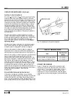
While the contactor is open, push the armature rearward
with a long screwdriver or other rod applied to the lower
end of the armature above the coil terminals. The
armature should not move because it should be firmly
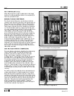
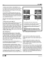
against the glass polyester main frame. See Figure 11.
To correct a problem, see Changing Operating Coil
under CONTACTOR MAINTENANCE.
Disconnect the extension cord and restore the plug into
its socket on the contactor chassis.
CHECK-OUT, VACUUM INTERRUPTERS
The dielectric strength of the interrupters should be
checked before the contactor is energized for the
first time and regularly thereafter to detect at the earliest
possible date any deterioration in the dielectric strength
of the contact gap since this may result in an interruption
failure. Although an AC dielectric test is recommended, a
DC test may be performed if only a DC test unit is
available. A good vacuum interrupter will withstand a
16kV-60-Hz test or a 23kV-DC test across a .156-inch
(4-mm) contact gap. This is the nominal contact gap for a
new contactor. When performing DC tests, the voltage
should be raised to test value in discrete steps and held
for a period of one minute. When tested with an AC high
potential tester, expect a capacitance leakage current of
approximately 1.3 milliamperes. For a DC tester expect
5 microamperes. Any spark across the contact gap
indicates failure.
SOME DC HIGH POTENTIAL UNITS, OPERATING AS
UNFILTERED HALF-WAVE RECTIFIERS, ARE NOT
SUITABLE FOR TESTING VACUUM INTERRUPTERS,
BECAUSE THE PEAK VOLTAGE APPEARING
ACROSS THE INTERRUPTERS CAN BE
SUBSTANTIALLY GREATER THAN THE VALUE
INDICATED.
When a vacuum bottle is tested with voltage over 5000
volts across its open gap, there is some possibility of
generating X-rays. Test time should be minimized, and
personnel should not be closer than 10 feet (3 meters)
and preferably located behind some barrier. This is a
precaution until such time as the possible hazard is better
understood and standards are published.
Periodic dielectric tests across open contacts should not
be omitted on the basis of satisfactory contactor perfor-
mance since under certain operating conditions, the
contactor may perform satisfactorily even though one
vacuum interrupter has become defective.
The interval between periodic tests depends on the
number of operations per day, environmental factors, and
experience. It is a matter of operator judgment.
CHECK-OUT, MECHANICAL
One of the features of Ampgard
®
motor control is the inter-
locking of the contactor and isolating switch which prevents
opening the isolating switch when the contactor is closed,
and prevents closing the isolating switch if the contactor is
already closed due to some malfunction. Neither closing nor
opening of the isolating switch under load is permissable.
The isolating switch interlock arm does not move, except
when the isolating switch is being opened or closed.
Similarly, during the opening or closing of the isolating
switch, the interlock rod on the isolating switch drives the
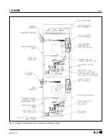
interlock arm of the SJS contactor clockwise so that the
heavy end moves down to keep the contactor from
closing. If the isolating switch interlock rod is not attached
to the interlock arm of the contactor by the clevis shown in
Figures 7 and 8, the natural weight of the interlock arm
moves the arm to a position which prevents the contactor
from closing.
All these interlocks are intended to protect against mal-
function. But they should be tested with main POWER
OFF prior to start-up (and at intervals thereafter) by
simulating improper operation and sequencing of the
contactor and isolating switch. Failure to interlock must be
corrected before power is applied.
CAUTION


