I.B. 48003
Page 16
Effective 11/97
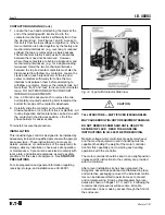
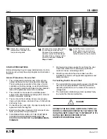
OPERATE THE ISOLATING SWITCH ONLY WITH ALL
DOORS CLOSED AND COMPLETELY LATCHED. THE
ISOLATING SWITCH MAY FAIL TO INTERRUPT IF ITS
RATING HAS BEEN EXCEEDED BY AN
UNDETECTED INTERNAL FAULT.
GENERAL MAINTENANCE
Ampgard
®
motor controllers should be operated and
maintained by authorized and qualified personnel only.
Personnel authorized to operate the isolation switch and
those authorized to inspect, adjust, or replace equipment
inside the enclosure should have a complete understand-
ing of the operation of the controller, and must have
thorough training in the safety precautions to be followed
when working with medium-voltage equipment.
MAINTENANCE PRECAUTIONS
There is a hazard of electric shock whenever working on
or near electrical equipment. Turn off all power supplying
the equipment before starting work. Lock out the discon-
necting means in accordance with NFPA 70E, “Electrical
Safety Requirements for Employee Safety In the Work-
place.” Where it is not feasible to de-energize the sys-
tem, take the following precautions:
a) Instruct persons working near exposed parts that are
or may be energized to use practices (including
appropriate apparel, equipment and tools) in accor-
dance with NFPA 70E.
b) Require persons working on exposed parts that are
or may be energized to be qualified persons who
have been trained to work on energized circuits.
For the purpose of these instructions, a qualified person
is one who is familiar with the installation, construction, or
operation of the equipment and the hazards involved. In
addition, this person should have the following qualifica-
tions:
a) Be trained and authorized to energize, de-energize,
clear, ground, and tag circuits and equipment in
accordance with established safety practices.
b) Be trained in the proper care and use of protective
equipment, such as rubber gloves, hard hat, safety
glasses or face shields, flash clothing, etc., in accor-
dance with established practices.
c)
Be trained in rendering first aid.
d) Be knowledgeable with respect to electrical installa-
tion codes and standards, for example, the National
Electrical Code (NEC).
MAINTENANCE PROGRAM
A maintenance program should be established as soon
as the controller has been installed and put into opera-
tion. After the controller has been inspected a number of
times at monthly intervals and the conditions noted, the
frequency of inspection can be increased or decreased to
suit the conditions found.
Before attempting maintenance, consult the specific
circuit diagrams supplied with the controller.
Insulation Level
After installation, and before energizing the controller for
the first time, the insulation resistance between poles,
and from each pole to ground should be measured and
recorded. It is not practical to specify an absolute value
for this reading since it is dependent on other connected
apparatus and conditions of service. However, any
unusually low reading or abrupt reduction in a reading
would indicate a possible source of trouble, and the
cause should be investigated and corrected.
Fuses
Inspect the current-limiting fuses after each fault-clearing
operation, since this is the most severe service to which
they will be subjected. Check the fuse resistance, and
compare this value with a new fuse. A visual sign of an
open fuse is provided by a colored indicator in the top of
the fuse. This indicator pops up and is visible when the
fuse is blown.
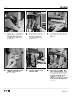
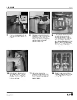
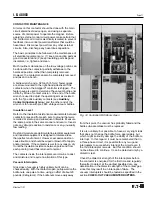
Use the fuse puller to remove and replace blown fuses.
The fuse puller is stored alongside the contactor rail. The
correct procedure for replacing fuses is described on the
operating instruction panel which is permanently fastened
inside the door to the medium-voltage compartment.
This instruction panel also lists the correct fuse rating
and fuse part number for that particular starter. The
same type, rating and part number of power circuit fuses
must be used for replacement in all cases. If preferred,
fuses may be removed and replaced by hand.
If for any reason, there is doubt about the condition of a
fuse, a simple test is to check its electrical continuity and
resistance.
DANGER

