I.B. 48003
Page 18
Effective 11/97
CONTACTOR MAINTENANCE (Continued)
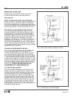
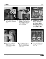
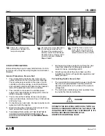
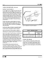
Contact Wear Allowance
Contact material vaporizes from the contact faces during
every interruption and condenses elsewhere inside the
bottle. This is normal, and is provided for by overtravel,
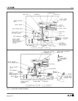
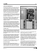
or wear allowance. When the contactor is fully closed,
there is a gap between the lower bottle nut and a pivot
plate. See Figure 12. As the contacts wear, this gap
decreases. When the gap goes below .020 inch (.51
mm) on any pole, all the bottle subassemblies should be
replaced. Use the .020-inch (.51-mm) thick fork-shaped
overtravel feeler gauge supplied for this measurement,
part no. 5259C11. DO NOT RE-ADJUST THE BOTTLE
NUTS TO RESET OVERTRAVEL AS THE CONTACTS
WEAR. Once placed into service, overtravel should be
checked but not adjusted.
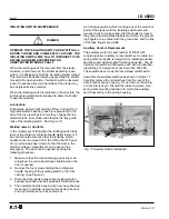
Inspection After Short Circuit Or Overload
The Type SJD contactor is intended to be protected by
power circuit fuses in accordance with the NEC. How-
ever, the magnitude of a short circuit may exceed the
damage threshold of the vacuum bottles. After the
interruption of any short circuit, particularly after a major
one that might have been near the maximum MVA rating
of the controller, examine the unit for any apparent
physical damage, or deformation of conductor bars and
cables. If there is any evidence of severe stress, all
bottle subassemblies must be replaced. If the overtravel
has changed significantly (from the last inspection) on
one or more bottles, replace all bottle subassemblies.
A dielectric test does not by itself confirm that the bottles
should be returned to service after a fault. However, if
there is no physical evidence of stress, and if the
overtravel exceeds the .020-inch (.51-mm) minimum, the
bottles can then be dielectrically tested as outlined
previously. If physical stress, overtravel, and dielectric
test results are within acceptable limits, it is reasonable to
return the contactor to service after a fault.
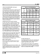
Magnet Operating Range
When properly adjusted as described in previous sec-
tions, the contactor should operate within the ranges
shown in Table II.
Operating Coil
The standard operating coils are shown in Table III. They
should be supplied directly from an AC or DC source with
sufficient volt-ampere capacity to maintain coil voltage
during inrush while closing. No external resistors are
required.
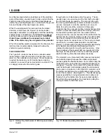
Changing Operating Coil
The contactor operating coil has a pick-up winding which
is intermittently rated. It may burn out in only minutes if
continuously energized at rated voltage and the L63
auxiliary contact does not open correctly.
The coil contains its own rectifier to convert applied AC
into unfiltered full-wave rectified DC. When parts are in
alignment and the coil is at rated voltage, the magnet will
be silent. At reduced voltage, a slight hum is acceptable.
However, the magnet must not chatter.
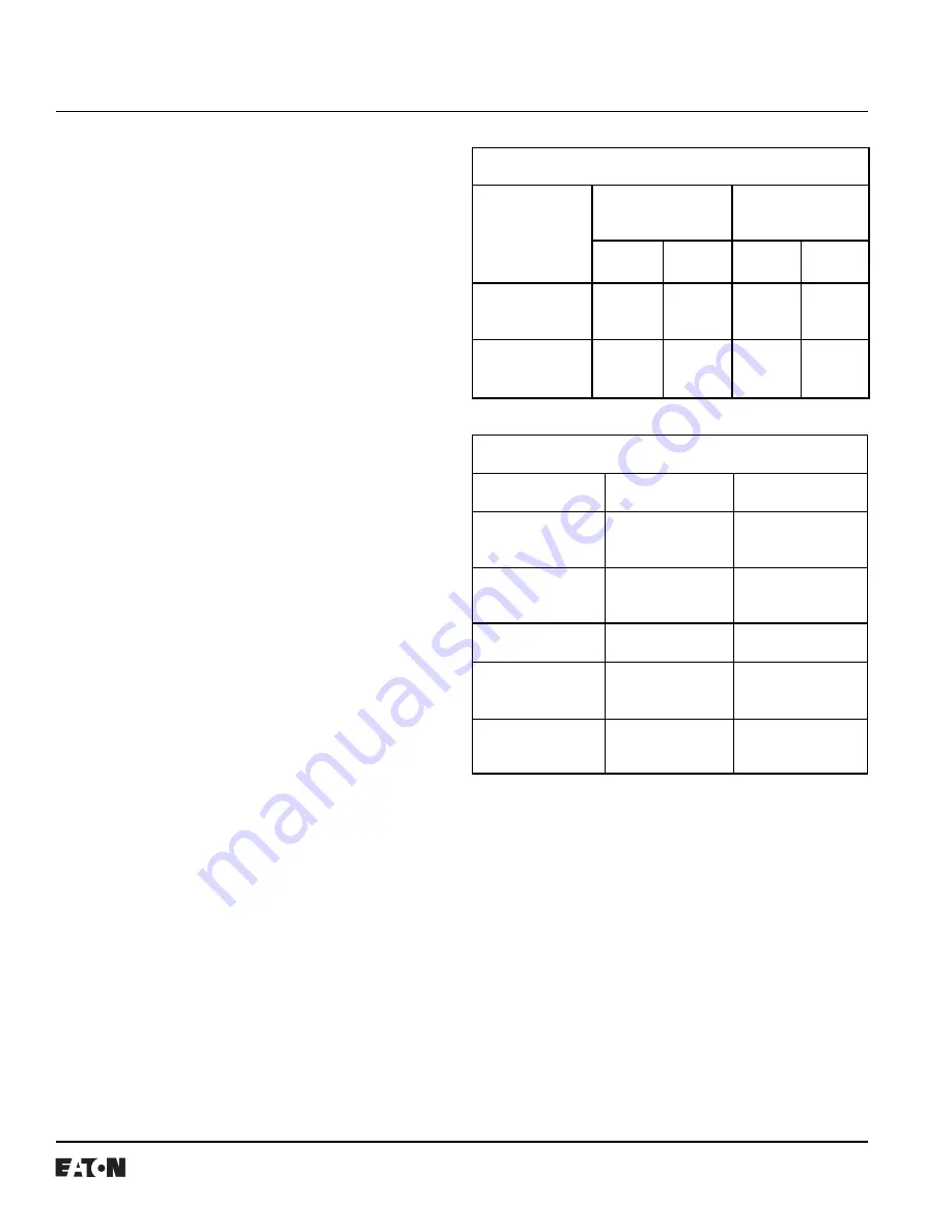
TABLE II. COIL PERFORMANCE
Rated
Coil
Voltage
Pick-Up-To-Seal
Voltage
Drop-Out-To-
Full-Open
Voltage
Above
Below
Below
Above
110-120 VAC
50
96
75
10
125 VDC
55
100
82
11
220-240 VAC
100
192
150
20
250 VDC
110
200
164
22
TABLE III. OPERATING COILS
Coil Part No.
7860A34G02
7860A34G04
AC Rating
110-120 VAC
220-240 VAC
50-60Hz
50-60Hz
AC Inrush
1300 VA
1400 VA
AC Sealed
25 VA
26 VA
DC Rating
125 VDC
250 VDC
DC Inrush
1500 VA
1600 VA
DC Sealed
28 VA
29 VA
Replacement
2147A48G11
2147A48G21
Coil Kit Part No.


