background image

I.B. 48003

Page 2

Effective 11/97

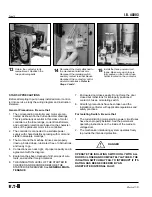
THE CONTROLLER (Cont.)

While this instruction booklet is dedicated to full-voltage
starting, the other applications listed are an expansion of
the same principles shown.

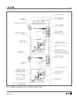
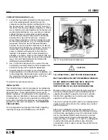
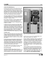
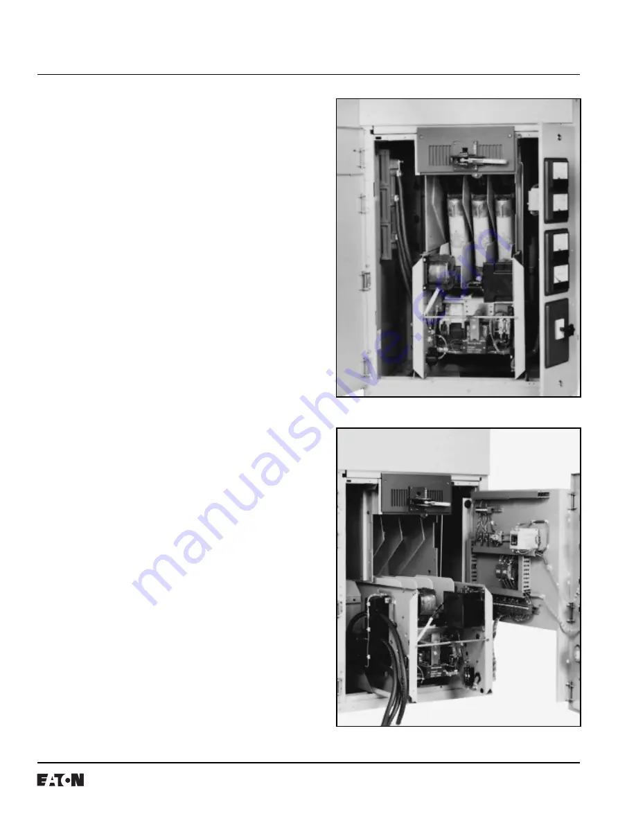
MEDIUM-VOLTAGE COMPONENTS

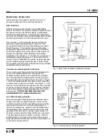
The flow of current through a vacuum-break controller
(starter) can be traced by referring to the upper portion of
Figure 4, where the controller is shown in the energized
position. The line stab assembly mounted at the back of
the enclosure also serves as the controller line terminals
(1). The stabs themselves are engaged by the fuse jaws
(2) of the isolating switch which is mounted on rails above
the contactor. The ferrules (3) of the current-limiting
motor-starting power circuit fuses (4) clip into the fuse
jaws, and the load ferrules (5) fit into the fuse holders (6)
which are part of the contactor line terminals. Current
flows through the contactor from the load ferrules of the
power circuit fuses, through the shunts (7), and the
vacuum interrupters (bottles) of the contactor (8), to the
contactor load terminals (9). Cables (10) pass through
current transformers and connect the contactor load
terminals to the controller load (motor) terminals mounted
on the enclosure wall to the left of the isolating switch.
See Figure 2. Connect the conductors from the motor to
these latter terminals.

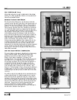
LOW-VOLTAGE CONTROL COMPONENTS

The low-voltage components consisting of an interposing
relay, protective relays, and optional equipment are
generally mounted on a slide-out panel.  The single-
phase control power transformer is bolted to the
contactor frame.  The capacity of this transformer ranges
from 600 VA to 2 kVA, depending upon requirements.
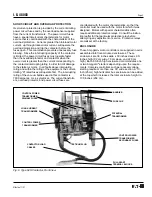
The primary winding of the control power transformer is
connected to the line through the power circuit fuse
assembly, and is protected by two additional low rating
current-limiting fuses mounted on the contactor.  See
Figure 6.  The secondary of the control power transformer
supplies power to the 120 (or 240) volt grounded control
circuit through secondary fuses mounted next to the test-
run plug.

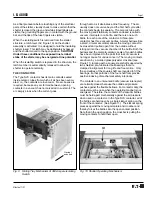
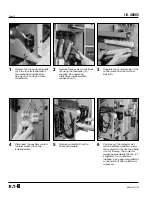
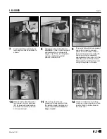
The slide-out panel and attached door constitute the low-
voltage compartment for most Ampgard motor controls.
This panel and door combination may be removed from
the base enclosure by first removing four machine screws
from the top and bottom rail bayonets on the back side of
the panel and lifting the panel up until the bayonets clear
their slots.  These screws must be replaced when the
panel is reinstalled to maintain stability.  Pull-apart
terminal blocks permit mechanical and electrical separa-
tion from the contactor. See Figure 6.

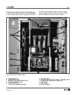
Fig. 2  SJS Contactor & Isolating Switch

Fig. 3  Low-Voltage Compartment

Summary of Contents for Cutler-Hammer Ampgard SC9000

Page 1: ...shown in Table I The controller may also be used to switch transformer windings or capacitor banks Each Ampgard controller occupies all or a portion of a steel structure that may also enclose a horizontal bus system to distribute power to two or more sections and a vertical bus system in each section con nected to the horizontal main bus system The controllers are configured for full voltage or re...

Page 2: ...ch See Figure 2 Connect the conductors from the motor to these latter terminals LOW VOLTAGE CONTROL COMPONENTS The low voltage components consisting of an interposing relay protective relays and optional equipment are generally mounted on a slide out panel The single phase control power transformer is bolted to the contactor frame The capacity of this transformer ranges from 600 VA to 2 kVA depend...

Page 3: ...I B 48003 Page 3 Effective 11 97 Fig 4 Ampgard Components Two Starters Controllers Shown ...

Page 4: ... mounted between phases and also between the two outside poles and the isolating switch end plates This isolating switch is a nonload break device It must never close or interrupt a power load However it does have a limited capacity for interrupting the single phase control power and potential transformers exciting current In terms of transformer ratings the maximum load is the equivalent of an un...

Page 5: ...tor is 7600 amperes r m s symetrical The current transform ers overload protector and power circuit fuses are coordinated with the motor characteristics so that the controller must be used with the motor for which it was designed Motors with special characteristics often require additional protective relays Consult the instruc tion leaflet for that particular protective relay before attempting any...

Page 6: ...witch Interlock There is also a mechanical interlock that is designed to prevent the isolating switch from closing with the contactor already closed and to prevent the contactor from closing while the isolating switch is being opened This latter state the transition phase is shown in Figure 7 With the isolating switch fully open or fully closed the contactor may be opened or closed See Figure 8 If...

Page 7: ...for each pole of the contactor A three pole contactor has three vacuum bottles A metal bellows like a small circular accordion allows the moving contact to be closed and pulled open from the outside without letting air into the vacuum chamber of the bottle Both the bellows and the metal to ceramic seals of modern bottles have been improved to the point that loss of vacuum is no longer cause for un...

Page 8: ... fuses are mounted directly above the contactor as for example in the case of one contactor in a reversing controller no barriers are required or furnished CONTACTOR MOUNTED COMPONENTS To simplify installation and servicing a number of related components are mounted on the Type SJS contactor chassis a control power transformer with test plug and fuses instrument quality potential transformers with...

Page 9: ...I B 48003 Page 9 Effective 11 97 Fig 11 Type SJS Contactor Positions ...

Page 10: ... barriers for easier access To reinstall reverse the procedure INSTALLATION This industrial type control is designed to be installed by adequately trained and qualified personnel with appropri ate supervision These instructions do not cover all details variations or combinations of the equipment its storage delivery installation check out safe operation or maintenance Care must be exercised to com...

Page 11: ...low voltage cables may be conveniently arranged near the right hand enclosure wall See Figure 3 G ISOLATING SWITCH H ISOLATING SWITCH AUXILIARY CONTACT TERMINAL BLOCKS J ISOLATING SWITCH MECHANICAL INTERLOCK K FUSE PULLER L LOAD CABLES M MOTOR TERMINALS A POSITIONING BOLTS B POWER CIRCUIT FUSES C MEDIUM VOLTAGE COMPARTMENT DOOR D CONTROL TERMINAL BLOCKS E VACUUM CONTACTOR F LOW VOLTAGE COMPARTMENT...

Page 12: ...ge door C 3 Separate the contactor side of the control wires from the terminal block D 4 Disconnect the auxiliary contact terminal blocks H on the isolating switch 5 Remove contactor E with a sharp pull forward 6 Part way out the contactor will reach a balanced position Lower the contactor to the floor and slide it out of the way The contactor weighs approximately 160 lbs 73 kilograms If a contact...

Page 13: ... shown 10 Refer to load cable instruction tag located at motor terminals M for load wiring instructions Controller is now ready to wire both line and load 11 After wiring reverse the procedure to reassemble Slide the isolating switch in place and secure with two bolts Refer to Steps 7 and 8 12 Check to make sure each fuse clamp is in correct position in fuse locator Refer to instructions on the lo...

Page 14: ... material 6 THE INSULATION LEVEL OF THE STARTER IS CHECKED AND RECORDED BEFORE THE STARTER IS ENERGIZED See GENERAL MAIN TENANCE 14 Reconnect the clevis attached to the mechanical interlock arm Reconnect the isolating switch auxiliary contact terminal blocks Reconnect the contactor control wire terminal blocks Refer to Steps 3 and 4 15 Install the three power circuit fuses Make sure each fuse is f...

Page 15: ...eres Any spark across the contact gap indicates failure SOME DC HIGH POTENTIAL UNITS OPERATING AS UNFILTERED HALF WAVE RECTIFIERS ARE NOT SUITABLE FOR TESTING VACUUM INTERRUPTERS BECAUSE THE PEAK VOLTAGE APPEARING ACROSS THE INTERRUPTERS CAN BE SUBSTANTIALLY GREATER THAN THE VALUE INDICATED When a vacuum bottle is tested with voltage over 5000 volts across its open gap there is some possibility of...

Page 16: ...practices c Be trained in rendering first aid d Be knowledgeable with respect to electrical installa tion codes and standards for example the National Electrical Code NEC MAINTENANCE PROGRAM A maintenance program should be established as soon as the controller has been installed and put into opera tion After the controller has been inspected a number of times at monthly intervals and the condition...

Page 17: ...same manner and record Investi gate any abrupt reduction in resistance or any unusually low reading Dust and moisture are detrimental to electrical equipment and industrial equipment is designed to tolerate a less than perfect environment However excessive dust can cause trouble and should be wiped or blown off at appro priate intervals If the contactor is wet for any reason dry it until the insul...

Page 18: ... service after a fault However if there is no physical evidence of stress and if the overtravel exceeds the 020 inch 51 mm minimum the bottles can then be dielectrically tested as outlined previously If physical stress overtravel and dielectric test results are within acceptable limits it is reasonable to return the contactor to service after a fault Magnet Operating Range When properly adjusted a...

Page 19: ... for mechanical interference that prevents the magnet from sealing If there is no interference then the magnet itself may be misaligned The magnet gap can be seen from the left and the right sides with the help of a flashlight The stationary magnet can be aligned with a 0 50 inch 12 7mm diameter steel rod inserted into the two holes in the core of the magnet and used as a lever to put a corrective...

Page 20: ...bending the operating arm with the forked end of the bottle wrench See Figure 15 After an L63 auxiliary contact is replaced gap adjustment may be made by first loosening the jam nut on the operating arm with a 0 438 inch open end wrench The gap size is changed by rotating the 0 25 20 bolt Clock wise rotation will increase the gap distance Counter clockwise rotation will decrease the gap distance U...

Page 21: ...I B 48003 Page 21 Effective 11 97 Fig 16 Cable and Connection Diagram ...

Page 22: ... It is designed to hold the insulating shutter closed This latch may be deliberately by passed and the shutter moved to the open position Caution should be observed since the exposed line terminal stabs of the starter may be energized at line potential When the isolating switch is replaced in the structure the latch lever is automatically released to allow the shutter to operate normally Lubricati...

Page 23: ...tenance 16 Initial Insulation Level 16 Inspection After Short Circuit 18 Installation 10 Page Insulation Level 17 Isolating Switch 4 9 Isolating Switch Contactor Interlock 6 Isolating Switch Handle Positions 4 Isolating Switch Maintenance 22 Line Stab Insulating Shutter 6 Low Voltage Components 2 Low Voltage Cut Off Switch 4 Low Voltage Cut Off Switch Replacement 22 Lubrication 22 Magnet Operating...

Page 24: ...I B 48003 Page 24 Effective 11 97 Printed in U S A CCI Cutler Hammer 221 Heywood Road Arden NC 28704 ...

Reviews: