
I.B. 48003
Page 22
Effective 11/97
ISOLATING SWITCH MAINTENANCE
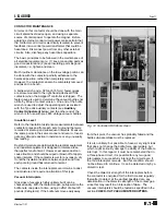
As a final precaution before touching any of the electrical
parts of the starter with the isolating switch removed,
visually check to make certain that the shutter is closed,
the green and white striped labels are visible, the ground-
ing fingers are in contact with the ground bar, and the tips
of the fuse fingers are visible.
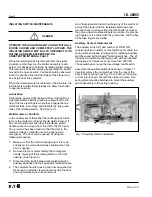
Auxiliary Contact Replacement
The auxiliary switch kit, part number 2147A01G01,
consisting of two auxiliary contact switches mounted to a
spring plate and leads, is designed for replacing auxiliary
switches used with Ampgard
®
isolating switches. The kit
includes two switch mechanisms, each with an inductive-
load rating of 20 amperes at not more than 250 VAC.
These switches serve as the low-voltage cutoff switch.
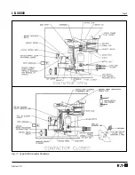
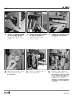
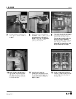
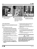
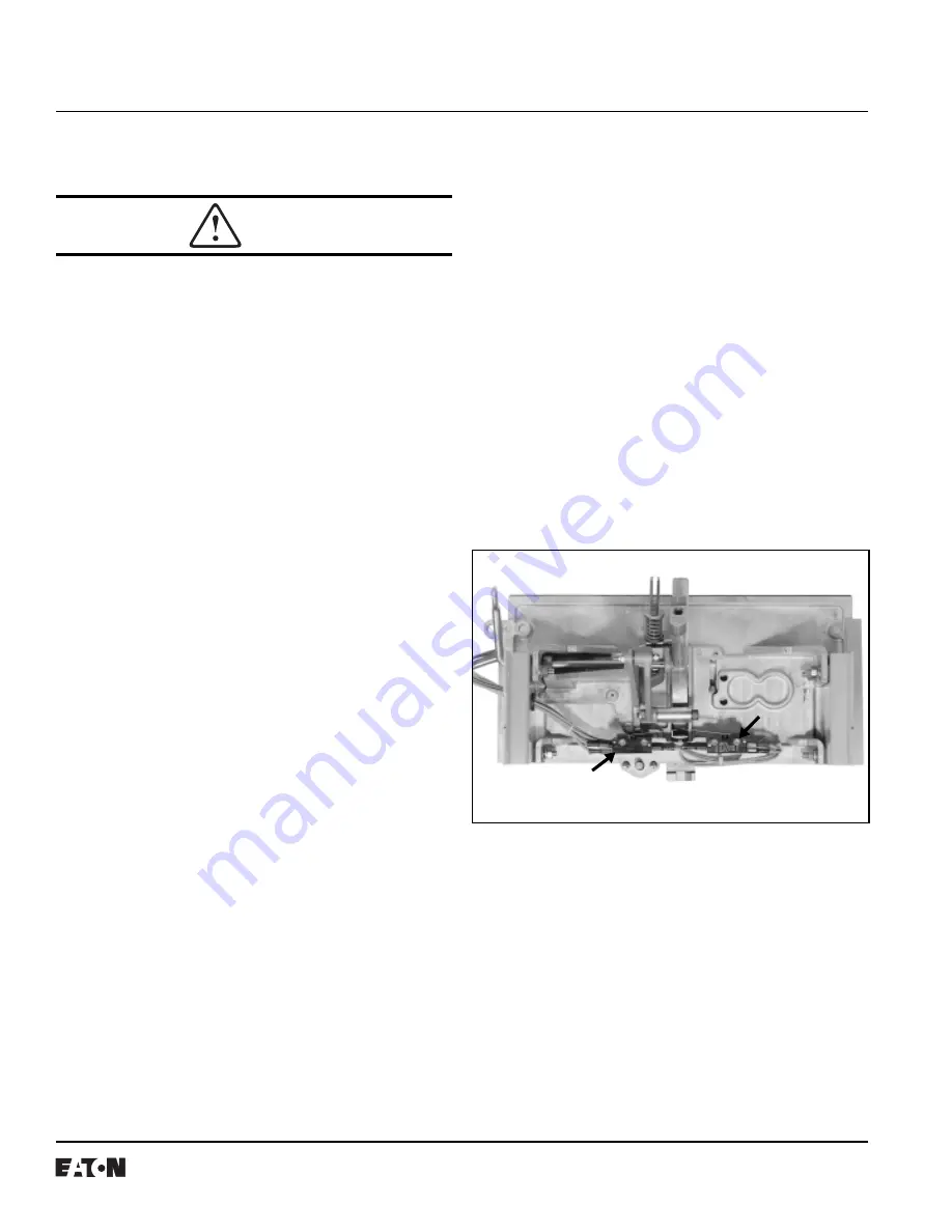
Assemble the auxiliary switches as shown in Figure 17.
Carefully remove the old switches from the rear of the
door interlock spring housing. Do not remove the spring
or door interlock pin. Discard the old spring plate. Use
spring plate mounting hardware to mount the auxiliary
switch assembly to the spring housing.
OPERATE THE ISOLATING SWITCH ONLY WITH ALL
DOORS CLOSED AND COMPLETELY LATCHED. THE
ISOLATING SWITCH MAY FAIL TO INTERRUPT IF ITS
RATING HAS BEEN EXCEEDED BY AN
UNDETECTED INTERNAL FAULT.
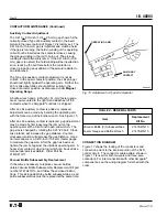
When the isolating switch is removed from the starter
structure, a latch lever on the shutter assembly is acti-
vated. It is designed to hold the insulating shutter closed.
This latch may be deliberately by-passed and the shutter
moved to the open position. Caution should be observed
since the exposed line terminal stabs of the starter may
be energized at line potential.
When the isolating switch is replaced in the structure, the
latch lever is automatically released to allow the shutter
to operate normally.
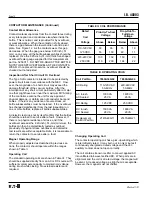
Lubrication
Periodically, apply a light coating of Dow Corning DC-4
high temperature silicone grease (or equivalent) to the
tips of the fuse jaw fingers where they engage the line
terminal stabs. Also clean and lubricate the tray guide
rails of the isolating switch. See Figure 10.
Welded Jaws or Contacts
In the unlikely event that either the isolating switch fuse
jaws or the contactor contacts should weld closed, or if
an event should occur such that the isolating switch
handle cannot be moved from the ON to the OFF posi-
tion, provision has been made so that the door to the
medium-voltage compartment can be opened in a
emergency. The door can be opened by using the
following procedure:
1.
Make sure that the main incoming power line is de-
energized, to avoid a hazardous situation when the
door is opened.
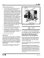
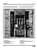
2.
Remove the four screws holding the rectangular
handle housing of the isolating switch to the front
casting. (See Figure 6.)
3.
Disconnect the leads between the isolating switch
auxiliary switches and their pull-apart terminal blocks.
4.
The complete handle housing can now be pushed up
far enough to provide clearance for opening the door
and any maintenance to be carried out.
DANGER
Fig. 17 Auxiliary Switch Installation