I.B. 48003
Page 5
Effective 11/97
SHORT-CIRCUIT AND OVERLOAD PROTECTION
Overcurrent protection is provided by the current-limiting
power circuit fuses and by the overload sensor supplied
from the current transformers. The power circuit fuses
have a special time/current characteristic for motor
service that is coordinated with the characteristic of the
overload protection. Currents greater than full-load motor
current, up through locked-rotor current, will operate the
overload protection and trip the contactor before the
fuses open. This coordination prevents unnecessary fuse
blowing. Since the interrupting capacity of the contactor
is limited, the power circuit fuses must operate faster
than the overload protector and contactor when the
overcurrent is greater than the current corresponding to
the contactor interrupting rating in order to limit damage
to the starter or motor. In all faults above interrupting
rating and within the rating of the equipment, the current-
limiting “R” rated fuses will operate first. The interrupting
rating of the vacuum bottles used in this contactor is
7600 amperes, r.m.s. symetrical.. The current transform-
ers, overload protector, and power circuit fuses are
coordinated with the motor characteristics, so that the
controller must be used with the motor for which it was
designed. Motors with special characteristics often
require additional protective relays. Consult the instruc-
tion leaflet for that particular protective relay before
attempting any adjustment or service. Protective relays
are not set at the factory.
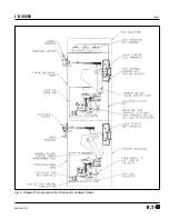
ENCLOSURE
These Ampgard
®
motor controllers are supplied in cells
assembled into floor-mounted enclosures. These
enclosures are 36 inches wide x 30 inches deep x 90-
inches high (92 cm wide, 76 cm deep, and 229 cm
high). Each 90-inch high enclosure accommodates one
or two Ampgard
®
starters depending upon the require-
ments. Complex controllers such as reduced-voltage
starting require more than one 36" wide section. A 10-
inch (25cm) high horizontal bus enclosure can be added
at the top which increases the total enclosure height to
100 inches (254 cm).
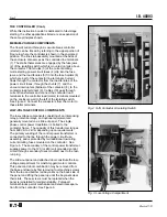
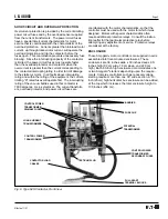
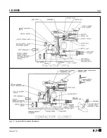
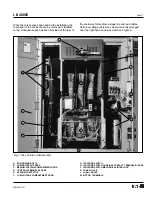
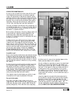
Fig. 6 Type SJS Contactor, Front View
BARRIER
FUSE CLIP
POTENTIAL
TRANSFORMER
CONTROL POWER
TRANSFORMER
SECONDARY FUSES
PULL-APART
TERMINAL BLOCKS
CONTACTOR LOAD
CABLES
TEST-RUN PLUG
CONTROL POWER
TRANSFORMER
LOAD-CURRENT
TRANSFORMERS
CONTROL POWER
TRANSFORMER
PRIMARY FUSES


