

I.B. 48003
Page 8
Effective 11/97
THE CONTACTOR (Continued)
The kickout spring is adjustable and occupies the space
above the operating magnet. The kickout spring must be
removed before the magnet coil can be changed if that
becomes necessary. The normal position of the kickout
spring lever is vertical. The lever can be loosened to
unload the kickout spring (after loosening the set screw
that locks the adjusting screw). Unscrew the 0.313-inch
adjusting screw immediately below the kickout spring
itself. Although it can be loosened, the lever is captive. As
the screw is loosened, the kickout spring will reach its
relaxed, free length and can be removed easily. To re-
install it, reverse the procedure. Insert the uncompressed,
free spring into position; then apply load by tightening the
adjusting screw on the lever until the lever is approxi-
mately vertical. See specific instructions later. Because
the spring forces exceed 100 pounds (45 kilograms),
place a free hand over the kickout spring as a precaution
while turning the adjusting screw in either direction.
Tighten the set screw to lock the adjusting screw.
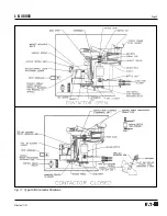
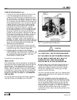
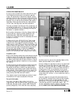
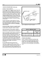
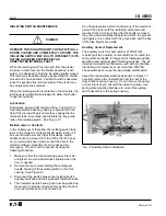
The operating magnet (see Figure 11) is on the front of
the contactor. The coil has a “figure-eight” shape and is
really two coils in series, with a connection to their
common point. Both coils are encapsulated in one
environmentally-immune coil shell, which also contains a
full-wave silicon diode rectifier. An AC or DC source can
be connected to terminals A and B on the coil shell.
When an AC source is applied, the rectifier converts the
AC to unfiltered DC to excite the magnet. When a DC
source is applied, only two legs of the full-wave rectifier
are active and pass DC current for magnet excitation.
The magnet will not chatter as AC magnets sometimes
do but at less than rated voltage, it may hum slightly. A
normally-closed auxiliary contact, set to open slightly
before the armature fully closes, is connected to termi-
nals C and D on the coil shell. When adjusted correctly,
this auxiliary contact allows a relatively high current
through the pick-up winding, and as the contactor closes,
the auxiliary contact inserts the holding winding, which
reduces the coil current to a low value, sufficient to hold
the magnet closed without overheating.
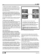
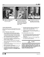
In the description of the bottles, it was mentioned that no
arc boxes are required. However, because of electrical
clearance requirements, four phase barriers must be
installed before the contactor is energized. Where
no fuses are mounted directly above the contactor,
as, for example, in the case of one contactor in a
reversing controller, no barriers are required or
furnished.
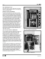
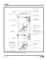
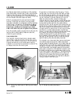
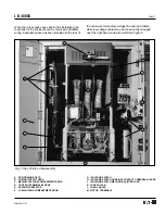
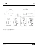
CONTACTOR-MOUNTED COMPONENTS
To simplify installation and servicing, a number of related
components are mounted on the Type SJS contactor
chassis: a control power transformer with test plug and
fuses, instrument-quality potential transformers with
secondary fuses (when furnished), primary fuses for the
control power and potential transformers, and load side
fuse clips for the power circuit fuses. See Figures 6 and
12. The test-run plug is used to connect to an auxiliary
source of control voltage when it is not inserted into the
receptacle that is the output from the secondary of the
control power transformer. This male test plug can be
plugged into a standard polarized 120-volt (or 240-volt,
depending on coil voltage rating) extension cord socket
for testing the control circuit and any sequence without
energizing the medium-voltage controller at power circuit
voltage. When the male plug is transferred to the exten-
sion cord, it automatically disconnects from the control
power transformer to prevent feedback of high voltage
into the power circuits. Check to be sure no inadvertent
bypass of this arrangement has been made in the wiring
before relying on this safety feature.
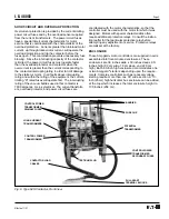
CONTACTOR HANDLING
Each contactor weighs about 160 pounds (73 kilograms).
An oblong hole is provided in each sidesheet for lifting if
desired.
A horizontal bar is provided at the front for pulling the
contactor out of its cell, or for pushing it back into place.
When a type SJS contactor is installed in a medium-
voltage controller it can be moved to a drawout position
or removed from the enclosure as follows:
WARNING: ALL WORK ON THIS CONTACTOR
SHOULD BE DONE WITH THE MAIN DISCONNECT
DEVICE OPEN. AS WITH ANY CONTACTOR OF THIS
VOLTAGE, THERE IS DANGER OF ELECTROCUTION
AND/OR SEVERE BURNS. MAKE CERTAIN THAT
POWER IS OFF. CHECK FOR VOLTAGE WITH
VOLTAGE SENSOR OR A METER OF THE
APPROPRIATE RANGE.
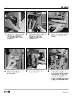
1.
If removal is planned, provide a lift truck or suitable
platform to receive the contactor as it comes out.
2.
Make sure all circuits are deenergized.
3.
Remove the three power circuit fuses using the fuse
puller supplied with the starter.
4.
Disconnect the control plug and stow it so that the
cable will not be damaged. Disconnect the two
3-point separable terminal blocks on the right front of
the isolating switch.
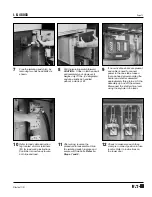
5.
Disconnect the isolating switch auxiliary contact pull-
apart terminal blocks located on the lower right-hand
side of the isolating switch.
6.
Disconnect the contactor load-side cables from the
controller load terminals.


