background image

September 2003

CA03310002E

For more information visit: 

www.cutler-hammer.eaton.com

23

NEMA Contactors & Starters

IT.

 Electro-Mechanical

Dimensions

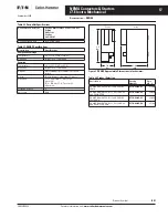
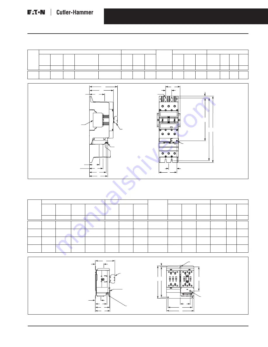
Non-reversing Starter (Size 5)

Table 29. Approximate Dimensions in Inches (mm) 

Figure 15. Approximate Dimensions in Inches (mm)

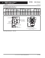
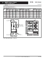
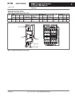
Reversing Starters (Sizes 00 – 4)

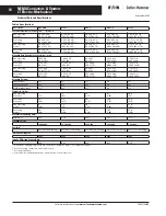
Table 30. Approximate Dimensions in Inches (mm) 

Figure 16. Approximate Dimensions — Inches (mm) 

NEMA
Size

Overall

Mounting Holes

Req. Mtg.
Screws

Reset Button 

Terminals

Width Length Depth Depth 

w/Logic
Level Auxiliary

Width 
w/Side
Auxiliaries

Width Height Mntg.

Hole
to Top

Width Height Depth Control Line

Load Load

A

B

C

D

E

F

G

I

K

L

M

N

P

Q

R

S

5

5.7
(145)

19.4
(492)

7.0
(178)

8.2
(208)

6.7
(170)

1.75
(44.5)

18.3
(465)

.58
(14.7)

(4) 5/16 
M8

2.4
(61)

12.4
(315)

5.3
(135)

5.0
(126)

4.4
(112)

3.0
(75)

4.0
(101)

NEMA
Size

Overall

Mounting Holes

Req. Mtg.
Screws

Reset Button 

Terminals

Width

Length

Depth

Depth w/
Auxiliary

Width

Height

Mtg. 
Hole to 
Top

Width

Height

Depth

Control

Line

Load

A

B

C

D

F

G

H

K

L

M

N

P

Q

R

00, 0

3.8
(96)

5.9
(149)

2.7
(69)

3.8
(96)

3.15
(80)

5.35
(136)

.28
(7)

(3) #10
M5

1.6
(40)

3.8
(97)

2.7
(68)

2.0
(50)

1.5
(38)

.9
(22)

1

4.5
(114)

5.9
(149)

2.6
(67)

3.8
(96)

3.15
(80)

5.35
(136)

.28
(7)

(3) #10
M5

1.7
(43)

4.1
(104)

2.6
(65)

2.0
(50)

1.5
(38)

.6
(16)

2

6.2
(158)

7.4
(188)

3.3
(84)

4.4
(112)

5.51
(140)

6.89
(175)

.24
(6)

(3) #10
M5

2.3
(58)

5.5
(139)

3.3
(83)

2.6
(67)

1.9
(48)

.9
(22)

3, 4

8.5
(216)

9.5
(242)

3.8
(97)

4.9
(125)

7.87
(200)

9.06
(230)

.24
(6)

(3) #10
M5

2.9
(73)

7.2
(182)

3.7
(94)

3.1
(80)

2.1
(54)

.7
(17)

Side

Auxiliary

Logic

Auxiliary

Control Terminal

Block

S

P

N

Load Terminals

(2 T1,  6 T3)

(4 T2)

R

A

L

Q

D

C

Line Terminals

(1 L1, 3 L2, 5 L3)

F

E

K

G B

M

H

Reset Button

.015 (.4)

Deflection

to Reset

Reset

Button

K

P

F

R

L

N

A

C

G

M

Control

Terminal Block

Reset Button

.015 (0.4)

Deflection to Reset

Dual Auxiliary –

Reduce Dim “D”

.3 (7) for the

Single Auxiliaries

B

Q

D

H

Line Terminals

(1 L1, 3 L2, 5 L3)

Load Terminals

(2 T1, 4 T2, 6 T3)

Summary of Contents for Cutler-Hammer CA03310002E

Page 1: ...scription Page IT Electro Mechanical 2 Product Family Overview 2 Catalog Number Selection 3 Contactors Full Voltage Non reversing and Reversing 4 Starters Full Voltage Non reversing and Reversing 7 Te...

Page 2: ...r and Starter User Manual Pub MN03403002E IT IEC Contactor and Starter User Manual Pub 50102 IT NEMA Overload Relay Quick Setup Guide Pub 49416 IT NEMA Contact Blocks Size 00 4 Pub 50140 IT NEMA Non r...

Page 3: ...mp overload range N02NCXCXNN Coil Controller 54 mm N04NBSAX3N Contact Block Size 00 Designator NEMA SA Size 00 S0 Size 0 S1 Size 1 S2 Size 2 S3 Size 3 S4 Size 4 S5 Size 5 XC Coil Controller XR Overloa...

Page 4: ...between the contactor and overload relay Conformal coated printed circuit boards for resistance to harsh environments Unique Pulse Width Modulated coil controller minimizes coil power consumption Micr...

Page 5: ...d accessories are available on Page 13 Integral solid state auxiliary hold in circuit See Table 7 for 24V DC power supply requirements Control inputs are rated 24V DC 3 5 mA Cat No N111BS0X3N NEMA Siz...

Page 6: ...Operated Reversing Contactors 24V DC coil voltage Note If required accessories are available on Page 13 Integral solid state auxiliary hold in circuit See Table 7 for 24V DC power supply requirements...

Page 7: ...d logic level 1NO 1NC Easily accessible mounting feet for panel mounting LED status indication trip trip class motor thermal state reset overload state Unique Alarm without Trip option for critical mu...

Page 8: ...Range Amperes Max UL Horsepower hp 60 Hz Max UL Horsepower hp 50 Hz 3 Pole Non reversing 1 Phase 3 Phase 3 Phase Catalog Number Price U S 115V 230V 200V 208V 230V 240V 460V 480V 575V 600V 380V 00 9 25...

Page 9: ...Continuous Ampere Rating Overload Adjustment Range Amperes Max UL Horsepower hp 60 Hz Max UL Horsepower hp 50 Hz 3 Pole Reversing 1 Phase 3 Phase 3 Phase Catalog Number Price U S 115V 230V 200V 208V 2...

Page 10: ...16 x 242 x 97 11 8 x 21 0 x 7 0 300 x 533 x 178 Mounting Hole Spacing in Inches mm w x h Non reversing Contactor 1 33 x 4 0 33 8 x 101 1 46 x 4 10 37 x 104 94 x 2 87 24 x 73 1 33 x 4 13 33 8 x 10⁵ 1 7...

Page 11: ...2 Wires per Terminal 14 AWG 1 5 mm2 14 AWG 1 5 mm2 14 AWG 1 5 mm2 14 AWG 1 5 mm2 14 AWG 1 5 mm2 P F R 1 2 3 1 Wire per Terminal 22 12 AWG 0 5 2 5 mm2 22 12 AWG 0 5 2 5 mm2 22 12 AWG 0 5 2 5 mm2 22 12...

Page 12: ...al Application AC 1 Non inductive or slightly inductive loads Resistance furnaces heating AC 2 Slip ring motors Starting and stopping of running motors AC 3 Squirrel cage motors Starting switching off...

Page 13: ...03NCXCXNN EMRKTC REVERSING KIT N511CS1X3N FVR Contactor Reversing Coil Controller Mechanical Interlock 2 Fanning Strips 2 NEMA Contact Blocks Mounting Plate EXAMPLE FOR A FULL VOLTAGE NON REVERSING CO...

Page 14: ...nge Amperes Catalog Number Price U S 00 0 25 8 59 1 9 1 4 4 4 2 8 9 0 6 3 20 N05NBXRA3A N05NBXRB3A N05NBXRC3A N05NBXRD3A N05NBXRG3A 74 50 74 50 74 50 74 50 74 50 0 10 32 N05NBXRJ3A 74 50 1 25 8 59 1 9...

Page 15: ...3 3 2NC EMA17 29 00 2 3 3 3 3 Logic Level 1NO 1NC EMA70 34 25 Auxiliary Contacts per Non reversing and Reversing Contactor or Starter Max Contact Type Description Catalog Number Price U S 2 1NO Base a...

Page 16: ...eNet MAC ID Manually set MAC ID and baud rate configuration using a software application is not required for normal operation Advanced configuration using CH Studio software Includes pre wired starter...

Page 17: ...8 to 176 F 50 to 80 C Humidity 0 95 non condensing Operating Temperature 13 to 131 F 25 to 55 C Humidity 0 95 non condensing Altitude Above 2000 meters 6600 feet consult factory Shock 15 g s half wave...

Page 18: ...w DIN Rail Width Height Mtg Hole to Top DIN Rail to Top Control Line Load A B C D E F G H J K P Q R 00 0 1 8 45 4 4 111 2 4 60 3 6 91 1 3 1 33 33 8 4 0 101 2 5 9 23 3 8 M4 7 19 1 2 30 1 2 30 1 2 1 54...

Page 19: ...3 4 6 x 2 M3 5 x 50 2 4 60 1 5 37 6 14 3 4 4 1 105 8 0 203 3 5 90 4 7 119 1 33 33 8 4 13 105 6 15 4 8 x 1 5 M4 x 40 2 8 72 1 7 42 3 8 NEMA Size Overall Mounting Holes Req Mtg Screws Terminals Width He...

Page 20: ...dth Height Mtg Hole to Top Control Line Load A B C D F G H K P Q R 00 0 3 8 96 5 9 149 2 7 69 3 8 96 3 15 80 5 35 136 3 7 3 10 M5 2 0 50 1 5 38 9 22 1 4 5 114 5 9 149 2 6 67 3 8 96 3 15 80 5 35 136 3...

Page 21: ...es mm NEMA Size Overall Mounting Holes Req Mtg Screws Terminals Width Height Depth Depth w Logic Level Auxiliary Width w Side Auxiliaries Width Height Mounting Hole to Top Control Line Load A B C D E...

Page 22: ...6 91 1 3 1 33 33 8 4 62 117 3 2 5 9 23 3 8 M4 6 14 3 6 91 2 5 63 1 7 44 1 2 30 6 16 1 2 1 54 5 4 138 2 5 63 3 6 91 1 3 1 46 37 5 04 128 2 5 8 20 3 8 M4 7 17 3 7 93 2 4 62 1 8 45 1 2 30 3 8 2 3 0 76 5...

Page 23: ...Req Mtg Screws Reset Button Terminals Width Length Depth Depth w Auxiliary Width Height Mtg Hole to Top Width Height Depth Control Line Load A B C D F G H K L M N P Q R 00 0 3 8 96 5 9 149 2 7 69 3 8...

Page 24: ...ximate Dimensions in Inches mm NEMA Size Overall Mounting Holes Req Mtg Screws Reset Button Terminals Width Length Depth Depth w Logic Level Auxiliary Width w Side Auxiliaries Width H1 Mntg Hole to To...

Reviews: