background image

PageS 

LOT w il l  reset itself. You can of course, manually 

clear the LOT (or any other trip indication) at any 
time, by pushing the "PUSH to RESET" button . 

(See  Figure 

1.) 

4.4  Short Delay Current Setting 

There are eight (8) available Short Delay Current Set­

tings,  as illustrated in  Fig. 4.3.  Six settings are in the 
range from 2 to 6 times 1, and the other two settings are 
"S1" or "S2" times 1,. (REMEMBER: 

I, 

is the Long Delay 

Current  Setting).  The  values that "S1" and "S2" have 

depend upon the type of circuit breaker, and are specified 

both on the rating plug label (see Fig.  6), and on the 
applicable Time-Current Curves referenced in 
Section 9.0. 

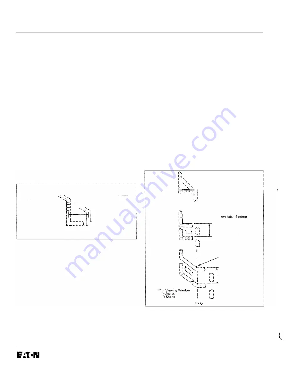
4.5 Short Delay Time Setting 

As illustrated in  Fig.  4.4, there are two different Short 

Delay curve shapes,  i.e., fixed time (flat) or  12t response. 
The  shape selected depends on the  type of selective 
coordination chosen. The  12t response will provide a 

longer time delay in the low-end of the short delay current 
range than will the flat response. 

f'>, 

Available  Settings 

r->-.... 

---·--

-· 

..... ,..,�"'_ 

S

hor

Delay 

j',, 

2, 2.5, 3. 4. 

Setting 

' .. �'_..,. 

5,  6, 

S,,  S, 

(5] 

1, 

''  Mol<'pt" of 

Long  Delay  Setting 

�-::� 

------�,) 

S1  and  S2 

Va

l

u

e

are 

Specified  on  Rating  Plug 

Fig.  4.3 

S hort Delay Current Settings 

Five flat (.1, .2,  .3, .4,  .5 sec.) and three 12t (.1 *,  .3*,  .5* 

sec.) response time delay settings are available. The 12t 
response settings are identified by the suffix asterisk 

(

*

that appears in the viewing window.  The 12t response is 
applicable to currents less than eight (8) times 1,, the 

Long Delay Setting. For currents greater than 8 times 1,, 

the 12t response reverts to the flat response. 

Note:  See also  Section 3.6, Zone Interlocking, above . 

4.6 Instantaneous Current Setting 

There are eight (8) available Instantaneous Current Set­

tings,  as illustrated in Fig. 4.5.  Six settings are in the 
range from 2 to 6 times (In) the rating plug value, and the 

I.L. 29-8858 

other two settings are "M1" or "M2" times (In)·  The values 
that "M1" and "M2" have depend upon the type of circuit 
breaker, and are specified both on the rating plug label 

(see Fig.  6),  and on the applicable Time-Current Curves 
referenced in Section 9. 0. 

4. 7 NO I nstantaneous Current Setting 

For types 

LS 

and 

LSG 

trip units, please see Sections 3.4 

DIScriminator (Making Current Release) and 3.5 OVER­

RIDE (Fixed Instantaneous), for available fast-acting high 

short-circuit protection. 

4.8 Ground Fault Current Setting 

The eight (8) Ground Fault Current Settings are labeled 

with the code letters "A" through 

"K" 

(except there are no 

"G" or "I" settings), as illustrated in Fig. 4. 6.  In general, 
the specific current settings range from  0. 25 to 1.0 times 

(In), the rating plug value, but cannot exceed 1200 A. The 

specific Ground Current Settings for each letter are listed 
in  Table 

and on the applicable Time-Current curve for 

the breaker. 

Sho.• Delay 

Time 

Sec. 

.1 

• .  

.. 

3, 

.• 

.5 

Seconds 

w1  h 

Flat 

Respon. 

Ft 

Shape 

Returns 

t

Flat 

Response 

at  Curre  lis 

Higher  than 

8  x  1, 

.

t

•, 

.34 

.5. 

Seconds 

with 

l>t 

Shape 

Fig.  4.4  Short Delay  Time S ettings 

Effective May 

1997 

(

www 

. ElectricalPartManuals 

. com 

Summary of Contents for Cutler-Hammer Digitrip RMS 510 Trip Unit

Page 1: ...ILE IT IS ENERGIZED DEATH OR SEVERE PERSONAL INJURY CAN RESULT FROM CONTACT WITH ENERGIZED EQUIP MENT ALWAYS VERIFY THAT NO VOLTAGE IS PRESENT BEFORE PROCEEDING WITH THE TASK AND ALWAYS FOLLOW GENERALLY ACCEPTED SAFETY PROCEDURES CUTLER HAMMER IS NOT LIABLE FOR THE MISAPPLICATION OR MISINSTAL LATION OF ITS PRODUCTS It is strongly urged that the user observe all recommen dations warnings and cautio...

Page 2: ...protection of the neutral circuit IF the circuit breaker is wired and MARKED for NEUTRAL PROTECTION Refer to the National Electric Code for appropriate application of 4 pole breakers 1 2 Information Light Emitting Diodes LED s on the face of the trip unit light Red to indicate the reason for an automatic trip operation The battery in the rating plug maintains the reason for trip indication followi...

Page 3: ...Protection LI Fig 2 2 Long Time Short Time Protection LS Effective May 1997 Fig 2 3 Long Time Short Time Instantaneous Protection LSI Page 3 Fig 2 4 Long Time Instantaneous Ground Protection LIG w w w E l e c t r i c a l P a r t M a n u a l s c o m ...

Page 4: ...me Instantaneous Ground Protection LSIG The Digitrip RMS 510 Trip unit provides three basic func tions Protection Information and Testing A typical trip unit and rating plug are illustrated in Fig 1 Individual product instruction leaflets referenced in Section 9 0 illus trate typical Digitrip RMS Trip Units installed in specific breakers T he trip unit employs the Cutler Hammer Inc custom designed...

Page 5: ...0 of the frame current sensor rating the green LED will flash On and Off onceeach second to indicate the trip unit is energized and operating properly Note If the LED is steadily GREEN i e not flash ing the trip unit is not ready Effective May 1997 3 3 Test Provisions See Section 5 0 3 4 DIScriminator Making Current Release For Types LS and LSG trip units only When the Digitrip RMS 510 Trip Unit i...

Page 6: ...ream breaker s trip unit to the input terminals of the upstream breaker s trip unit For specific instructions see the applicable connection dia grams for your breaker listed in Section 9 0 I L 29 8858 Note If a breaker M receives a Zone Interlocking signal from another breaker F but the fault current level is less than the trip unit setting for breaker M the signal from the other breaker F will no...

Page 7: ... earlier than the Long Delay Time Setting When the load current returns to normal the LTM begins to reset and after about 10 minutes it has reset fully so that next Long Delay trip time will again be the Set ting value In certain applications it may be desirable to dis able the LTM function The LTM function can be disabled by first opening the breaker and then removing the Rating Plug See Figures ...

Page 8: ...licable to currents less than eight 8 times 1 the Long Delay Setting For currents greater than 8 times 1 the 12t response reverts to the flat response Note See also Section 3 6 Zone Interlocking above 4 6 Instantaneous Current Setting There are eight 8 available Instantaneous Current Set tings as illustrated in Fig 4 5 Six settings are in the range from 2 to 6 times In the rating plug value and th...

Page 9: ...0 240 300 400 a w 600 150 180 210 240 300 360 450 600 Q_ 630 158 189 221 252 315 378 473 630 s 800 200 240 280 320 400 480 600 800 9 1000 250 300 350 J 400 500 600 750 1000 _J 1200 300 360 420 480 600 720 900 1200 Q_ 9 1250 312 375 438 500 625 750 936 1200 z 1600 400 480 560 640 800 960 1200 1200 a 2000 500 600 700 800 1000 1200 1200 1200 0 2400 600 720 840 960 1200 1200 1200 1200 w _J _J 2500 625...

Page 10: ...utomatic trip and test operations Push then release Test button to test Test operation begins with release of pushbutton Fig 5 Integral Test Panel Lower Right Corner of Trip Unit A CAUTION TESTING A CIRCUIT BREAKER UNDER TRIP CON DITIONS WHILE IT IS IN SERVICE AND CARRYING LOAD CURRENT WHETHER DONE BY INTERNAL OR EXTERNAL MEANS IS NOT RECOMMENDED ANY TRIPPING OPERATION WILL CAUSE DISRUP TION OF SE...

Page 11: ...s than10 of the breaker frame or current sensor rating be sure the GREEN Unit Status LED in the lower right corner of the trip unit See Figs 1 and 5 is blinking on and off indicating that there is enough current flowing to pro vide the power necessary to operate the trip unit In the event the Unit Status LED is either lighted GREEN or OFF continuously there is NOT enough cur rent flowing to power ...

Page 12: ...ng make sure the circuit breaker is carrying no more than 50 of the Long Delay Current Setting lr The I L 29 8858 trip unit will not execute your instructions to Test itself when the load current exceeds 50 of lr 2 Place the Test Amps selector switch See Fig 5 in one of the two Trip test settings i e 6T or GFT 3 Depress the black Test pushbutton See Fig 5 and release it the test is initiated when ...

Page 13: ...r Rat1ng Plug Identification Fig 6 Battery Check Pushbutton 1 Typical Rating Plug Values for Sho t Delay S1 and S2 Instantaneous M1 and M2 Set11llQS Battery OK if LED lights GREEN when Battery Check Button is Pushed Page 13 obtained from the following companies under their type designation indicated Company Model Varta Batteries Inc 150 Clarbrook Road Elmsford N Y 10523 Duracell South Broadway Tar...

Page 14: ...cuit breaker can carry with the specified current sensors installed The Sensor Rat ing can be the same or less than the Frame Rating but not greater The Rating Plug See Fig 6 fits into a special cavity to complete the trip unit See Fig 1 Rating plugs have two current ratings listed on their covers See Fig 6 1 the Must be used with Frame Rated cur I L 29 8858 rent value or Sensor Rated if applica b...

Page 15: ...me Circuit Breaker APPENDIX A ZONE INTERLOCKING Assume a ground fault of 2000 Amperes occurs and refer to Fig A 1 CASE 1 There is no Zone Selective Interlocking standard time delay coordination is used The branch breaker will trip clearing the fault in 0 1 s Fault 2 The feeder breaker will trip clearing the fault in 0 3 s Fault 1 The breaker will trip clearing the fault in 0 5 s CASE 2 There is Zo...

Page 16: ...he maximum distance between first and last zone is 250 feet 110 m A3 A Maximum of 20 breakers may be con nected in parallel in one Zone Legend Common Ungrounded Short Delay Output Signal to Higher Level Zone Short Delay Input Signal from Lower Level Zone Ground Output Signal to Higher Level Zone Ground Input Signal from Lower Level Zone ault at Location 2 2 M2 0 5 Sec F21 F22 F23 0 1 Sec 0 1 Sec 0...

Page 17: ...I L 29 8858 Page 17 NOTES Effective May 1997 w w w E l e c t r i c a l P a r t M a n u a l s c o m ...

Page 18: ...Page 18 I L 29 8858 NOTES Effective May 1997 w w w E l e c t r i c a l P a r t M a n u a l s c o m ...

Page 19: ...I L 29 8858 Page 19 0 NOTES Effective May 1997 w w w E l e c t r i c a l P a r t M a n u a l s c o m ...

Page 20: ...OSE OR MERCHANTABILITY OR WARRANTIES ARISING FROM COURSE OF DEALING OR USAGE OF TRADE ARE MADE REGARDING THE INFORMATION RECOMMENDATIONS AND DESCRIPTIONS CONTAINED HEREIN In no event will Cutler Hammer Inc be responsible to the purchaser or user in contract in tort including negligence strict liability or otherwise for any special indirect incidental or consequential damage or loss whatsoever incl...

Reviews: