I.L. 29-8858
r-. 1...,..1
I I
I
I
.......
Setting
lnst
I L
ITJx
In
:
--\
®
(S)
I_---
Available
S
ett
i n
gs
------
2. 2.5,
3. 4,
5. 6, M,, M,
In
Multiples
of
Rating Plug
Amperes
On)
M1
and
M2 Values
are Specified on Rating Plug
Fig.
4.5
Ins tantaneous Current Settings
Note: For Testing Purposes Only: When using an
external single phase current source to test low level
ground fault current settings, it is advisable to use
the Auxiliary Power Module (APM) (See Fig. 7). Espe
cially when the single phase current is low, without
the APM it may appear as if the trip unit does not
respond until the current is well above the set value,
leading the tester to bel ieve there is an error in the
trip unit when there is none. The reason this occurs
is that the single phase test current is not a good
simulation of the normal three phase circuit. If three
phase current had been flowing, the trip unit would
actually have performed correctly. Use the APM for
correct trip unit performance whenever single phase
tests are made.
Available Settings
Gnd-Fault
�
Setting
A. 8, C, D,
[J
xln
E.
F.
H, K
e
Specific
Values
Given
on
Ci
r
cuit
Breaker Time-Current
Curve and in Table
1
Fig.
4.6
Ground Fault Current Settings
Effective May 1997
Page 9
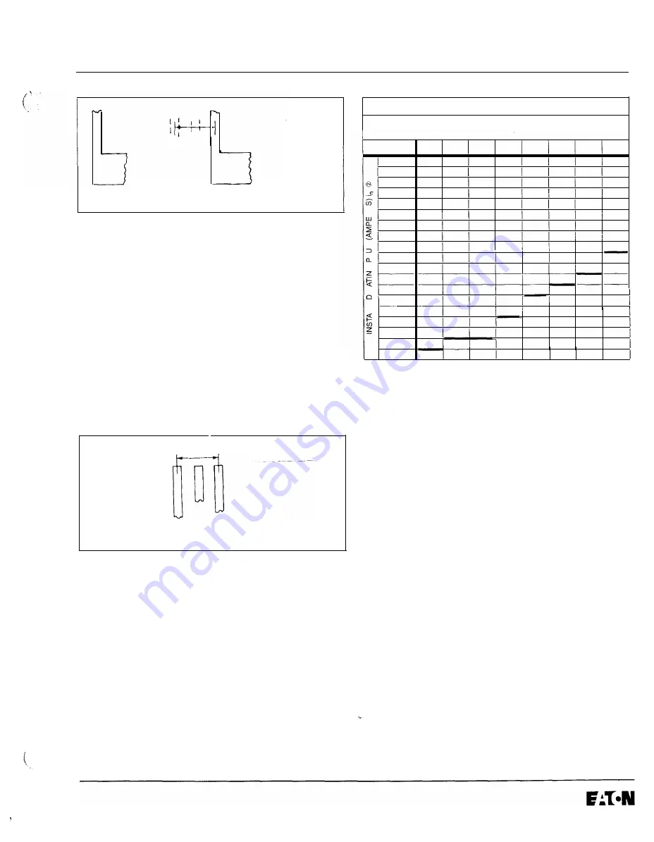
TABLE 1 -GROUND FAULT CURRENT SETIINGS
GROUND FAULT CURRENT SETTINGS
(AMPERES)
•
A
B
c
D
E
F
H
K
100
25
30
35
40
50
60
75
100
200
50
60
70
80
100
120
150
200
250
63
75
88
100
125
150
188
250
300
75
90
105
120
150
180
225
300
w
400
100
120
140
160
200
240
300
400
a:
600
150
180
210
240
300
360
450
600
630
158
189
221
252
315
378
473
630
800
200
240
280
320
400
480
600
800
(9
1000
250
300
350
400
500
600
750
1000
_J
1200
300
360
420
480
600
720
900
1200
(9
1250
312
375
438
500
625
750
936
1200
1600
400
480
560
640
800
960
1200
1200
a:
2000
500
600
700
800
1000
1200
1200
1200
2400
600
720
840
960
1200
1200
1200
1200
w
_J
_J
2500
625
750
875
1000
1200
1200
1200
1200
3000/3150
750
900
1050
1200
1200
1200
1200
1200
3200
800
960
1120
1200
1200
1200
1200
1200
4000
1000
1200
1200
1200
1200
1200
1200
1200
5000
1200
1200
1200
1200
1200
1200
1200
1200
CD
Tolerances on settings are
±1 0%
of values shown.
•2!
Refer to Type DS, type SPB or Series C R-Frame supplemental instruction
leaflets given in Section
9
for list of available rating plugs lor each type circuit
breaker.
4.9 Ground Fault Time Delay Setting
As illustrated in Fig.
4.7,
there are two different Ground
Fault curve shapes, i.e., fixed time (flat) or 12t response.
The shape selected depends on the type of selective
coordination chosen. The 12t response will provide a
longer time delay in the low-end of the ground fault cur
rent range than will the flat response.
Five flat
(.1, .2, .3,
.4,
.5
sec.) and three 12t
(.1*, .3*, .5*
sec.) response time delay settings are available. The 12t
response settings are identified by the suffix asterisk
(*)
that appears in the setting viewing window. The 12t
response is applicable to currents less than
0.625
times
the ampere rating of the installed rating plug
(In).
For c
u
r-
rents greater than
0.625
x
In
the 12t response reverts to
the flat response.
www
. ElectricalPartManuals
. com


