IL17569C
Page 5-54
FP-5000
Effective Date: 12/05
Page 5-54
For more information visit:
www.eatonelectrical.com
Effective Date: 12/05
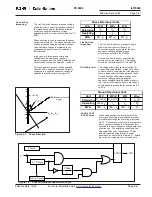
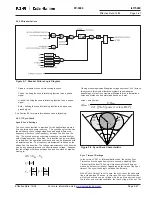
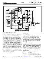
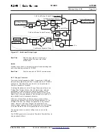
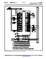
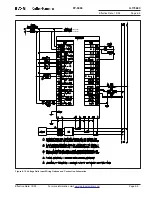
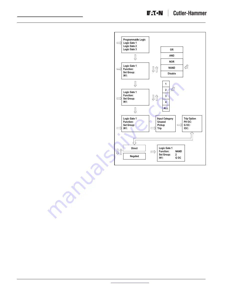
Figure 5-10. Logic Setting Flowchart
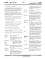
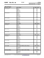
5.4.8 Cold Load Pickup Settings
A greater amount of current than normal load current may be
experienced due to the load inrush when manually or automatically
closing the breaker after it had been open for a prolonged time. This
high starting current causes some overcurrent elements to unneces-
sarily trip the breaker. The cold load pickup function prevents this
from happening. The cold load pickup function is initiated only if:
1) Cold load pickup control function is enabled.
2) The breaker had been opened for a specified amount
of time before closing.
3) Not in the process of auto-reclosing.
Once a cold load pickup control is initiated, the instantaneous
overcurrent elements, current unbalance and power protection
elements may be blocked at the user’s choice and the time inverse
overcurrent elements may also be desensitized at the user’s
choice. When the load current drops below a certain level for a
specified time all the OC elements will use the normal pickup
settings. The cold load pickup timeout setting is used for terminat-
ing the use of cold load pickup control if the load inrush diminishing
signal has not been received within the timeout. The cold load
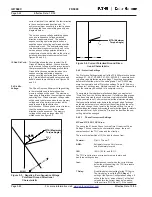
pickup threshold setting (P1 in figure 5-9) is an inrush current
indicator. When the load current exceeds this level, occurrence of
load in rush will be identified and the load inrush diminish timer will
be initiated.
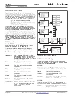
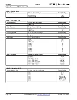
5.4.9 Clock Settings
Once the FP-5000 is properly installed, the real-time clock needs to
be set, to get the right date and time for clock display, and all
Metering and Logging date and time stamp values.
To set the clock, select the clock setting in the “Setting Main”
display window. Configure the settings below to set the clock.
Date Mode:
Sets the mode for the date used in all time
stamp displays.
Time Mode:
Sets the mode for the time used in all time
stamp displays. Choose 12 hour mode for AM
and PM display of the time. Choose 24 hour
mode for military display. Example; 1 P.M. would
be displayed as 13:00.
Year:
Sets the current year for the real-time
clock update.
Month:
Sets the current month for the real-time
clock update.
Day:
Sets the current day for the real-time
clock update.
Hour:
Sets the current hour for the real-time
clock update.
Minute:
Sets the current minute for the real-time
clock update.
Second:
Sets the current second for the real-time
clock update.
Update Clock:
Pressing Enter updates the clock with the date
and time specified above, with the message
stating that the real-time clock was
properly updated.
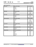
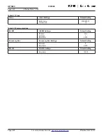
5.4.10 Communications Settings
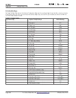
To set the communications settings, select the Communications
setting in the “Setting Main” display window. Configure the settings
below to set the communications desired.
INCOM PN
Provides connection to the IMPACC network for communication
over PowerNet. The standard IMPACC messages are supported.
Enable:
Enables INCOM Communication.
Address:
Sets the device address for INCOM
communication.
Baud Rate:
Sets the baud rate for INCOM communication.
The baud rate is fixed at 9600 baud.
INCOM AB
Provides an additional INCOM channel for future expansion to
interconnect function modules for analog and digital I/O accessories.
Address:
Sets the device address for Communication
through Accessory bus.


