IL17569C
Page 6-6
FP-5000
Effective Date: 12/05
Page 6-6
For more information visit:
www.eatonelectrical.com
Effective Date: 12/05
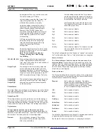
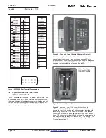
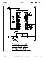
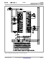
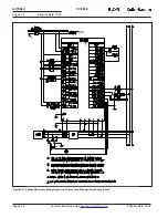
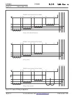
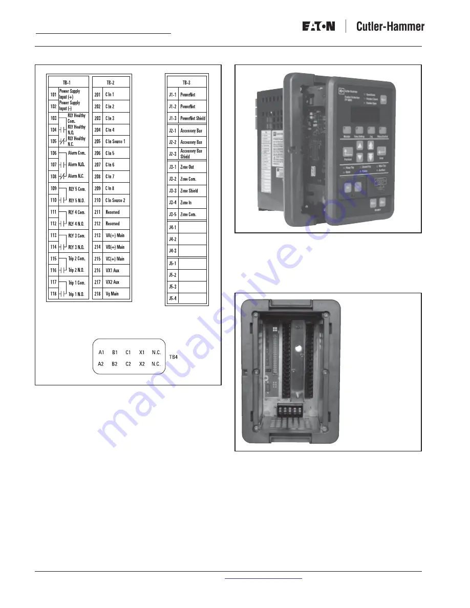
Figure 6-5. FP-5000 Rear Terminal Designations
6.4 Separated Draw-out Case Views
with Internal Callouts
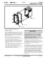
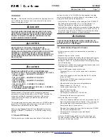
The FP-5000 assembly is shown in
Figure 6-6
prior to installation.
The chassis is shown as it is when withdrawn from the case. When
withdrawn, the make-before-break connectors within the case will
provide a short across the current transformers (CT) inputs. This
provides protection for the CTs in the event that the chassis is
withdrawn while the current transformers are under power.
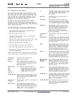
Figure 6-6. Case with Inner Chassis Withdrawn (Drawout)
When removing the chassis from the case, care must be taken as
many electronic components and circuits are exposed. Service
personnel should use electrostatic wrist straps to avoid damage due
to electrostatic discharge (ESD). Touching the metal chassis prior to
handling may reduce the risk of damage due to ESD.
1
Card Edge Connectors
2
J Connector TB3
3
Current Connectors
1
1
1
1
1
2
2
2
2
2
3
3
3
3
3
1
1
1
1
1
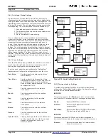
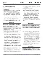
Figure 6-7. Internal View of Case Connectors
Figure 6-7
provides a view of the case with the chassis fully
withdrawn from the FP-5000 assembly. Several connectors can be
seen in the rear of the enclosure. These connectors interface with
their mating connectors of the Chassis. There are two card edge
connectors, TB1 and TB2 (See
Figure 6-4
FP-5000 Rear Connec-
tions). TB1 connector is primarily used for the ac/dc power input and
also relay contacts for relay RLY1 through RLY7, TB2 is used for the
contact inputs and the phase voltage inputs. (See
Figure 6-5
Rear
Terminal Designations.)

