FP-5000
IL17569C
Page 8-5
Effective Date: 12/05
Effective Date: 12/05
For more information visit:
www.eatonelectrical.com
Page 8-5
Nominal Current
The nominal primary current I
nom
, as measured by the FP-5000, is
established by the ratio of the selected current transformers. This
ratio must by set via the programming of the relay under “System
Config” in the Setting Main menu. These settings must agree with
the current transformers to which the relay is connected. Therefore,
I
nom
is established by the current transformer ratio used and
becomes the primary scale factor for the trip functions and readouts.
Before proceeding with the curve explanation, it should be noted that
combining functional capabilities, such as inverse time overcurrent,
short delay and instantaneous, is a coordination activity. The effects of
one group of settings on another should be understood in order to
determine if the results are acceptable under all foreseeable circum-
stances. This helps to avoid unexpected operations or non-operations
in the future. Keep in mind that the FP-5000 operates its trip/alarm
algorithms simultaneously and independently. If any one of the
algorithms detects a trip condition, the FP-5000 will trip, even though
the user may expect one of the other trip curves (algorithms) to
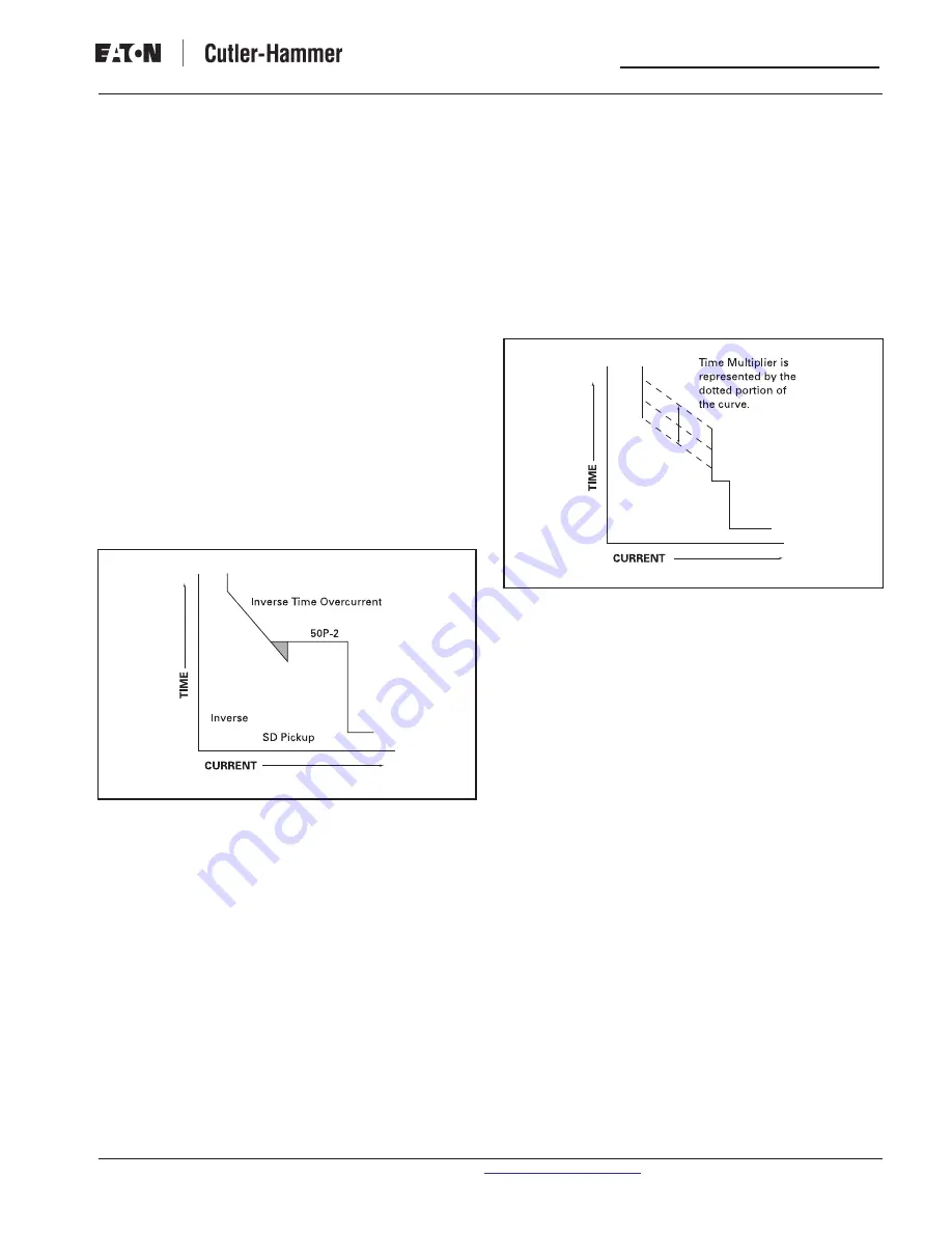
prevail. For instance, if the Inverse Time Overcurrent calculation
results in a time which is less than the 50P-2 trip time, the FP-5000
will trip; it will not cease ITOC evaluation within the operative domain
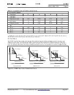
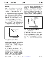
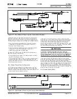
of the 50P-2 evaluation. (See
Figure 8-7
.) The shaded portion of the
curve illustrates the ITOC value less than the 50P-2 Delay time. For
the FP-5000, the ITOC time will prevail. The programmable logic
may be configured to prevent tripping in this region if desired.
Figure 8-7. Typical Curve with l
2
t Shape
Inverse Time Overcurrent Protection
Inverse time overcurrent protection consists of a curve shape, pickup
setting, and an inverse time multiplier setting. The inverse time
overcurrent function offers 10 possible curve shape types as
previously described (
Figure 8-4
and Table 8.1). When programming
the FP-5000, this will be the first choice to make. The curve shape
and its effect on the characteristic curve will be covered with the time
multiplier explanations.
The pickup setting establishes the current level pickup at which the
relay’s inverse time overcurrent tripping function begins timing. If,
after a predetermined amount of time, the current condition that
started the timing process still exists, the inverse time overcurrent
function operates and the relay’s trip relay is energized. Pickup
settings can be adjusted from 0.10 to 4.00 times I
nom
.
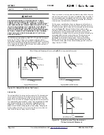
Figure
8-6
graphically illustrates how the beginning of the Thermal Inverse
Time Overcurrent Pickup portion of the overall curve can be moved
horizontally on the time current grid by means of the pickup settings.
The Inverse Time Overcurrent Pickup is represented by the dotted
lines, while the rest of the curve is represented by a solid line.
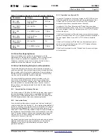
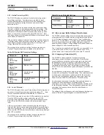
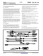
Figure 8-8.
Typical Time Multiplier Adjustment
(I
2
t Response)
The Time Multiplier setting is used to select a predetermined amount
of time a sustained overload condition will be carried before the
breaker trips. For the Thermal Curves, a setting is entered by
determining the trip time needed at a 3 X I
nom
overcurrent for phase
faults and I
nom
for ground faults. This value is then divided by 5. For
the ANSI and IEC curves, this represents a pure multiplication of
the curve as viewed in Section 8.3.2. A wide range of time settings
are available for curve shape selection. As Time Multiplier settings
are varied, the Time Multiplier portion of the overall curve is moved
vertically up or down on the time current grid. This movement is also
independent of the other portions of the curve.
Figure
8-8
graphi-
cally illustrates the vertical time line movement with an I
2
t curve shape
selection. Similar movement occurs for the remaining curve shapes.
Timed Overcurrent Protection
Two timed overcurrent functions are provided each for phase I
a
, I
b
, I
c
,
I
x
and I
r
. The pairs are: [50P1, 50P2], [50X1, 50X2] and [50R1, 50R2].
If desired they may be used for the traditional Instantaneous
Overcurrent function and the Short Time Delay Overcurrent function.
Instantaneous, is achieved by setting the time delay to zero. In most
cases the number 1 overcurrent function is set as the instantaneous,
and the number 2 as the short delay. However, the setting ranges
are identical for the two sets of curves, and they may be set as the
user desires.

