FP-5000
IL17569C
Page 8-9
Effective Date: 12/05
Effective Date: 12/05
For more information visit:
www.eatonelectrical.com
Page 8-9
8.6 Voltage Functions and Protection
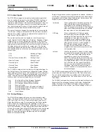
8.6.1 Negative Sequence Voltage Protection (47)
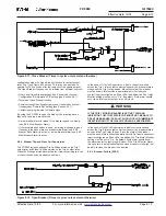
The FP-5000 provides monitoring and protection based on the
percent of voltage unbalance or negative sequence voltage. The
presence of negative sequence voltage identifies either a phase
unbalance or reverse phase rotation condition. The positive and
negative sequence voltages are calculated from the three phase
voltages. The % unbalance is the ratio of negative sequence
voltage to positive sequence voltage (%Unbalance = V
2
/V
1
). A
voltage unbalance pickup occurs when V
2
/V
1
exceeds the VUB %
Unbalance setting and the V
1
or the V
2
magnitude exceeds the VUB
Threshold setting. The Voltage Unbalance trip is set when the pickup
condition exists for the delay time specified. The voltage unbalance
pickup and trip is reset when the positive sequence voltage drops
below the VUB Threshold setting or V
2
/V
1
drops below the VUB %
Unbalance setting minus 1%.
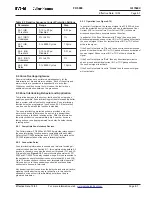
The settings associated with voltage unbalance or negative
sequence voltage protection are listed in Table 8.3 below.
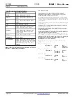
Table 8.3 Negative Sequence Voltage Protection
Parameter
Range
Step
47-1 VUB
1 to 100 V,
1 V
Threshold
Disabled
47-1 VUB %
2% to 40%
1%
Unbalance
47-1 VUB
0 to 9999 Cycles
1 Cycle
Delay
47-2 VUB
1 to 100 V,
1 V
Threshold
Disabled
47-2 VUB %
2% to 40%
1%
Unbalance
47-2 VUB
0 to 9999 Cycles
1 Cycle
Delay
8.6.2 Undervoltage (27) and Overvoltage (59) Protection
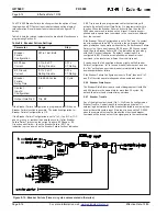
Separate undervoltage and overvoltage protective elements are
provided for the main voltage inputs (V
A
, V
B
, V
C
) and the auxiliary
voltage input (V
X
). Two elements are provided for each function so
alarm and trip levels can be set independently. Each of the voltage
protection functions has a Threshold, a Delay setting and the main
voltage elements have an additional setting - phase. The optional
time delay is provided for coordination with other devices.
An overvoltage pickup occurs when the measured voltage exceeds
the OV Threshold setting. The overvoltage trip flag is set when the
voltage exceeds the threshold setting for the delay time specified.
The overvoltage pickup and trip is reset when the voltage drops
below 98% of the OV Threshold setting.
An undervoltage pickup occurs when the measured voltage drops
below the UV Threshold setting. The undervoltage trip is set when
the voltage stays below the threshold setting for the delay time
specified. The undervoltage pickup and trip is reset when the voltage
raises above 102% of the UV Threshold setting.
The Main OV and UV Pickup and Delay settings apply to all three
phase voltages, V
A
, V
B
and V
C
. 27M and 59M pickups and trips are
controlled by their phase setting.
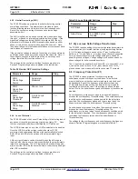
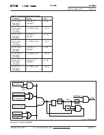
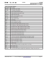
Table 8.4 Voltage Protection Settings
Parameter
Range
Step
59-M1 Main
Any One, Any Two,
Overvoltage Phase
All Three
59-M1 Main
10 to 150 V,
1 V
Overvoltage Threshold Disabled
59-M1 Main
0 to 9999 Cycles
1 Cycle
Overvoltage Delay
59-M2 Main
Any One, Any Two,
Overvoltage Phase
All Three
59-M2 Main
10 to 150 V,
1 V
Overvoltage Threshold Disabled
59-M2 Main
0 to 9999 Cycles
1 Cycle
Overvoltage Delay
27-M1 Main
Any One, Any Two,
Undervoltage Phase
All Three
27-M1 Main Under-
10 to 150 V,
1 V
voltage Threshold
Disabled
27-M1 Main
0 to 9999 Cycles
1 Cycle
Undervoltage Delay
27-M2 Main Under-
Any One, Any Two,
voltage Phase
All Three
27-M2 Main Under-
10 to 150 V,
1 V
voltage Threshold
Disabled
27-M2 Main
0 to 9999 Cycles
1 Cycle
Undervoltage Delay
59-A1 Auxiliary
10 to 250 V,
1 V
Overvoltage
Disabled
Threshold
59-A1 Auxiliary
0 to 9999 Cycles
1 Cycle
Overvoltage Delay
59-A2 Auxiliary
10 to 250 V,
1 V
Overvoltage
Disabled
Threshold
59-A2 Auxiliary
0 to 9999 Cycles
1 Cycle
Overvoltage Delay
27-A1 Auxiliary
10 to 250 V,
1 V
Undervoltage
Disabled
Threshold
27-A1 Auxiliary
0 to 9999 Cycles
1 Cycle
Undervoltage Delay
27-A2 Auxiliary
10 to 250 V,
1 V
Undervoltage
Disabled
Threshold
27-A2 Auxiliary
0 to 9999 Cycles
1 Cycle
Undervoltage Delay
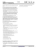
The settings for the voltage protection functions are shown in
Table 8.4.

