IL17569
Page 8-8
Effective June, 2001
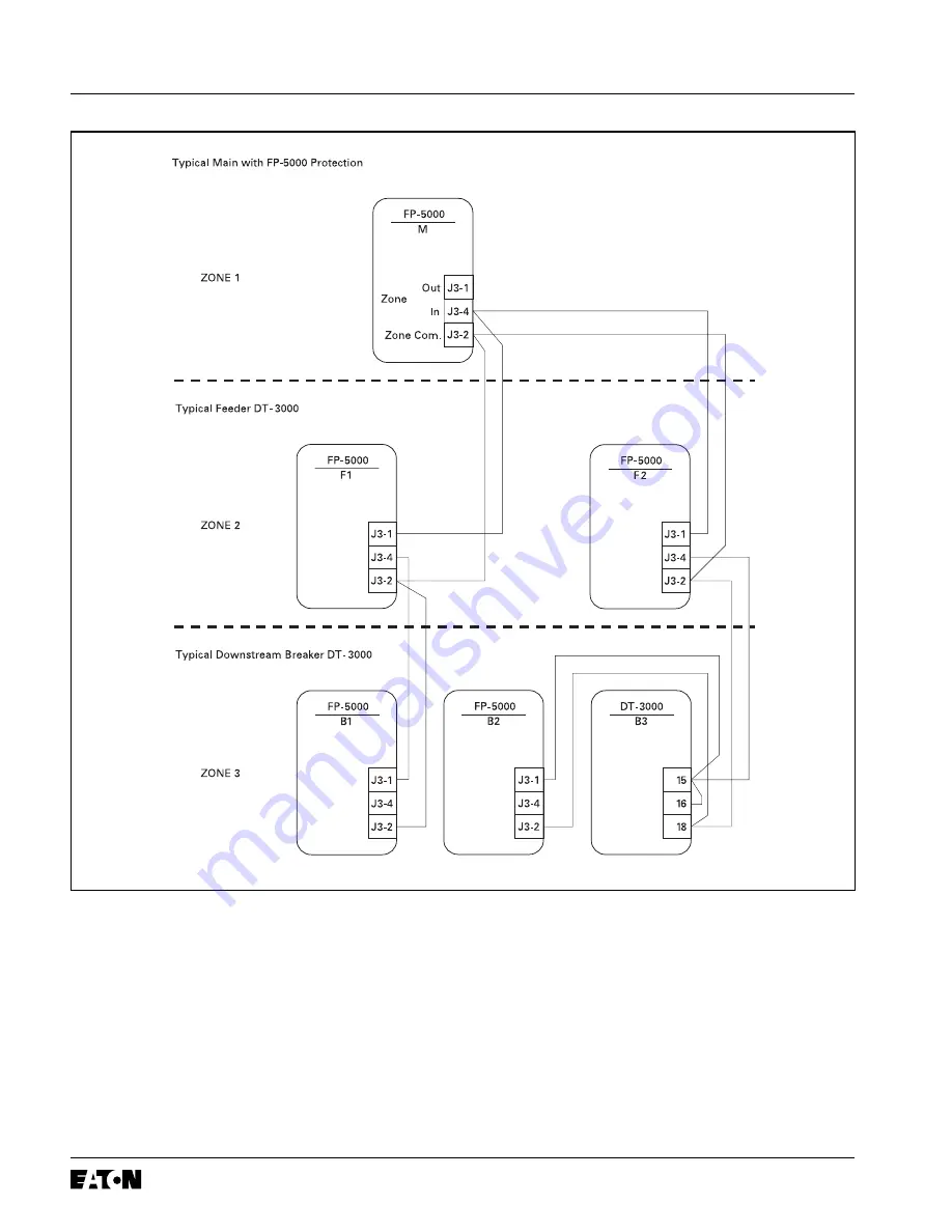
Figure 8-10. Zone Interlocking Example with FP-5000 and DT-3000
In general, if the Zone Interlocking Input is enabled, the absence of
a zone-in signal active, and an IOC or TOC pickup occurs, an
immediate trip will occur. The immediate trip has a 3-cycle pickup
delay to make sure the downstream devices have a chance to
activate the zone interlock signal. If the zone-in signal is active, then
the programmed delay time is used.
If the Zone In setpoint is set to “Phase” then any phase current
above of the IOC pickup or
1.5 times
the TOC pickup will cause an
immediate trip in the absence of an active zone-in signal. Ground or
residual current IOC or TOC will not cause an immediate trip. The
1.5 time multiplier is used so that a low level current overload does
not cause an immediate trip. If the zone-in signal is active then the
programmed delay time is used.
If the Zone In setpoint is set to “Ground” then any ground or residual
current above the IOC pickup or the TOC pickup will cause an
immediate trip in the absence of an active zone-in signal. Phase
current IOC or TOC will not cause an immediate trip. If the zone-in
signal is active then the programmed delay time is used.
In the case that the breaker that is taking action fails to open the
circuit, the zone-out signal is removed in one of two ways:
1. If the breaker fail function is active then the zone out signal is
immediately removed. See Section 5 Programming on page 5-1
and Section 8.9 Breaker-Oriented Functions.
2. If the protective relay has operated but the current is still sensed,
the zone-out signal is removed 10 cycles after the operation.
Summary of Contents for Cutler-Hammer FP-5000
Page 1: ...IL17569 Effective June 2001 Instructions for FP 5000 Protective Relay...
Page 7: ...IL17569 Table of Contents 6 Effective June 2001 This page left blank intentionally...
Page 13: ...IL17569 Page 2 2 Effective June 2001 Figure 2 2 FP 5000 Simple Wye Connected Application...
Page 14: ...Page 2 3 IL17569 Effective June 2001 Figure 2 3 FP 5000 Simple Open Delta Application...
Page 19: ...IL17569 Page 2 8 Effective June 2001 This page left blank intentionally...
Page 25: ...IL17569 Page 3 6 Effective June 2001 This page left blank intentionally...
Page 98: ...IL17569 Page 5 50 Effective June 2001 This page left blank intentionally...
Page 108: ...IL17569 Page 6 10 Effective June 2001 Figure 6 10 Common Ct Wiring Configurations...
Page 141: ...IL17569 Page 11 4 Effective June 2001 This page left blank intentionally...
Page 165: ...IL17569 Page Appendix 6 Effective June 2001 Figure 13 2 ANSI Very Inverse...
Page 166: ...Page Appendix 7 IL17569 Effective June 2001 Figure 13 3 ANSI Extremely Inverse...
Page 167: ...IL17569 Page Appendix 8 Effective June 2001 Figure 13 4 IEC A Figure 13 4 IEC A...
Page 168: ...Page Appendix 9 IL17569 Effective June 2001 Figure 13 5 IEC B...
Page 169: ...IL17569 Page Appendix 10 Effective June 2001 Figure 13 6 IEC C...
Page 170: ...Page Appendix 11 IL17569 Effective June 2001 Figure 13 7 IEC...
Page 171: ...IL17569 Page Appendix 12 Effective June 2001 Figure 13 8 ANSI...
Page 172: ...Page Appendix 13 IL17569 Effective June 2001 Figure 13 9 Thermal...
Page 173: ...IL17569 Page Appendix 14 Effective June 2001 Figure 13 10 Phase I4 t...
Page 174: ...Page Appendix 15 IL17569 Effective June 2001 Figure 13 11 Phase I2 t...
Page 175: ...IL17569 Page Appendix 16 Effective June 2001 Figure 13 12 Phase It...
Page 176: ...Page Appendix 17 IL17569 Effective June 2001 Figure 13 13 Phase 12 I4 t...
Page 177: ...IL17569 Page Appendix 18 Effective June 2001 Figure 13 14 Phase I2 t...
Page 178: ...Page Appendix 19 IL17569 Effective June 2001 Figure 13 15 Ground IT...
Page 180: ...Page Appendix 21 IL17569 Effective June 2001 This page left blank intentionally...
Page 187: ...Publication No IL17569 June 2001 Pittsburgh Pennsylvania U S A...


