IL17569
Page 4-22
Effective June, 2001
4.6.5 Set
The “
Set
” pushbutton can be accessed through
the security door on the front panel (See
Figure
4-1
). Once the “
Set
” pushbutton is activated, a
password screen will show up on the display.
The password must be entered to change the
FP-5000 settings. To enter the password, use
the “
single
” up/down arrow pushbutton to
change the selected character of the password
and use the “
double
” up/down arrow
pushbutton to change the value of the character.
Once the password is entered, the user must
then press the “
Enter
” pushbutton to enter the
password and to activivate the setting screens.
See Section 5 for a complete description of the
FP-5000 product settings.
4.6.4 Status/Control
Press the “Status/Control” pushbutton to view
all of the FP-5000 status and control param-
eters. The red LED in the upper left-hand
portion of the pushbutton area will illuminate
while you are in the Status/Control Mode.
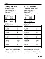
Display 4.17 shows the options displayed by
activating the “Status/Control” pushbutton.
Display 4.17 Status/Control
Total History Log
Display Meanings
Operate Hours:
Number of house of operation.
# Power Up:
Number of times powered up.
# IOC Trips:
The number of instantaneous
overcurrent trips.
# TOC Trips:
The number of time
overcurrent trips.
# Unbal Trips:
The number of phase
unbalance trips.
# Volt Trips:
The number of voltage
related trips.
# Total Trips:
The total number of trips.
# Bkr Ops:
The number of breaker
operations.
IA Accum:
Phase A accumulated
interrupted amps.
IB Accum:
Phase B accumulated
interrupted amps.
IC Accum:
Phase C accumulated
interrupted amps.
RstTime:
The time stamp of the last
History Log reset.
RstDate:
The date of the last
History Log reset.
Display 4.16 Breaker History Log
Breaker History Log
Display Meanings
# Bkr Op:
0
The number of breaker
operations.
IA Accum:
0
Phase A accumulated
interrupted amps.
IB Accum:
0
Phase B accumulated
interrupted amps.
IC Accum:
0
Phase C accumulated
interrupted amps.
RstTime:
00:00:00
The time stamp of the last
Breaker Log reset.
RstDate:
00/00/00mdy
The date of the last
Breaker Log reset.
Status/Control
Status
Control
Version
Copyright
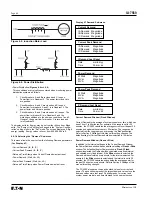
By using the Up/Down pushbutton and scrolling down through the
menus, the user can view additional information about the status of
all inputs, outputs and control logic of the FP-5000 relay (see
Display 4.18 below). “Version” display gives the user access to view
the version of the product’s boot code and application code.
Status
Self Test Status
Active Set Group: 1
Input Status
Output Status
Logic Status
Pickup Status
Trip Status
System Alarm Status
Breaker Status
Display 4.18 Status
Control
Sel Active Set Grp
Default Settings
Trigger Datalogger
Trig Waveform Capt
Version Info
Boot Code
Application
Copyright 2001
Eaton Corporation
All Rights Reserved
By selecting the “Control” sub-menu, the user can set the FP-5000
control parameters as shown in the “Control” display. See Section 5
for programming the control parameters.
Display 4.15 Total History Log
Summary of Contents for Cutler-Hammer FP-5000
Page 1: ...IL17569 Effective June 2001 Instructions for FP 5000 Protective Relay...
Page 7: ...IL17569 Table of Contents 6 Effective June 2001 This page left blank intentionally...
Page 13: ...IL17569 Page 2 2 Effective June 2001 Figure 2 2 FP 5000 Simple Wye Connected Application...
Page 14: ...Page 2 3 IL17569 Effective June 2001 Figure 2 3 FP 5000 Simple Open Delta Application...
Page 19: ...IL17569 Page 2 8 Effective June 2001 This page left blank intentionally...
Page 25: ...IL17569 Page 3 6 Effective June 2001 This page left blank intentionally...
Page 98: ...IL17569 Page 5 50 Effective June 2001 This page left blank intentionally...
Page 108: ...IL17569 Page 6 10 Effective June 2001 Figure 6 10 Common Ct Wiring Configurations...
Page 141: ...IL17569 Page 11 4 Effective June 2001 This page left blank intentionally...
Page 165: ...IL17569 Page Appendix 6 Effective June 2001 Figure 13 2 ANSI Very Inverse...
Page 166: ...Page Appendix 7 IL17569 Effective June 2001 Figure 13 3 ANSI Extremely Inverse...
Page 167: ...IL17569 Page Appendix 8 Effective June 2001 Figure 13 4 IEC A Figure 13 4 IEC A...
Page 168: ...Page Appendix 9 IL17569 Effective June 2001 Figure 13 5 IEC B...
Page 169: ...IL17569 Page Appendix 10 Effective June 2001 Figure 13 6 IEC C...
Page 170: ...Page Appendix 11 IL17569 Effective June 2001 Figure 13 7 IEC...
Page 171: ...IL17569 Page Appendix 12 Effective June 2001 Figure 13 8 ANSI...
Page 172: ...Page Appendix 13 IL17569 Effective June 2001 Figure 13 9 Thermal...
Page 173: ...IL17569 Page Appendix 14 Effective June 2001 Figure 13 10 Phase I4 t...
Page 174: ...Page Appendix 15 IL17569 Effective June 2001 Figure 13 11 Phase I2 t...
Page 175: ...IL17569 Page Appendix 16 Effective June 2001 Figure 13 12 Phase It...
Page 176: ...Page Appendix 17 IL17569 Effective June 2001 Figure 13 13 Phase 12 I4 t...
Page 177: ...IL17569 Page Appendix 18 Effective June 2001 Figure 13 14 Phase I2 t...
Page 178: ...Page Appendix 19 IL17569 Effective June 2001 Figure 13 15 Ground IT...
Page 180: ...Page Appendix 21 IL17569 Effective June 2001 This page left blank intentionally...
Page 187: ...Publication No IL17569 June 2001 Pittsburgh Pennsylvania U S A...


