IL17569
Page 5-34
Effective June, 2001
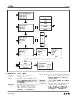
5.5.2. Protection Settings
The Protection Settings include all of the FP-5000 protective device
settings: 27, 46, 47, 50, 50BF, 51, 55A, 55D, 59, 81, zone interlock-
ing, and protection alarm settings. The setting descriptions below
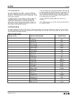
will follow the order of the setting table. The FP-5000 may store
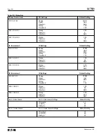
four complete sets of Protection settings. Table 5.1 lists only
settings for 1 setting group. Multiple copies of the Protection
section from the table may be needed for a complete record.
To navigate to the individual protection settings you must select
“Protection” from the Setting Main menu. If multiple setting groups
have been selected then you must select which protection setting
group you wish to set. You must now select the protection elements
that you want to set and enter down to the set point page. To change
an individual set point you must select the setting, press the enter
button and change the set point to the desired setting. You must
acknowledge the change by pressing the enter button again to return
to the previous level. If you press the “Previous” button then the
new setting will not be changed.
5.5.2.1
Phase Overcurrent Settings
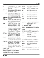
51P PH TOC Curve:
This is the 51 device Phase Inverse Time Overcurrent Curve
Setting. The user selects the characteristic
shape
and the
reset
characteristic of the TOC curve. The FP-5000 will have directional
capability in the future. The direction setting is fixed at
Both
.
There are three families of TOC curves to choose from:
Thermal:
Flat, It, I
2
t, and I
4
t
ANSI:
Extremely Inverse, Very Inverse,
and Moderately Inverse
IEC:
IEC-A, IEC-B, and IEC-C
The TOC
reset
is a time overcurrent memory feature and
has three setting choices:
Inst:
Instantaneous reset: when the current drops
below the pickup setting, the TOC time resets
to zero within 2 cycles.
T Delay:
Fixed time delay reset setting for the TOC curve.
The time delay is set to the
TOC Reset T
setting of the System Configuration Settings. It
will hold the time (“percent travel”), at the last
value before the current drops below pickup,
for the set time (TOC Reset T). If the current
value goes above pickup before the reset time
has expired then the relay will begin to accu-
mulate time from its last value (percent travel).
“Percent Travel” refers to the percent of the
time delay that the timer has accumulated. The
time overcurrent time is dynamic. If the current
changes it will change its trip times to the new
value. Total trip time will be the time at which
the accumulator reaches 100%. For example,
if the current is at level 1 for 40% of the total
trip time based on level 1 current then the
accumulator will be at 40%. If the current now
changes to level 2 with a new trip time, then
the remaining trip time will be 60% of the new
trip time. So the total trip time will be 40% of
trip time t
1
plus 60% of trip time t
2
. If the current
was to drop below pickup for a time less
than the TOC Reset T in between level 1 and
level 2 currents, then the total trip time will
include the time below pickup to the total trip
time calculated. This feature could be beneficial
to tripping for an arcing fault condition.
Calc:
Calculated reset, which is defined by ANSI
C37.112. This setting represents the
electromechanical induction disk model and
best integrates in a system utilizing E/M relays.
T
reset
= (t
r
x D) / [(I/I
pu
)
2
– 1] where t
r
is a curve
constant and D is the time multiplier. See
Section 8 for more information.
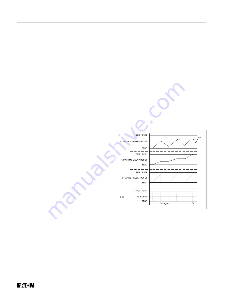
Figure 5.1
provides a graphical representation of the three reset
characteristics. The rms current value is the bottom square wave
and assumes that the current level is either above or below the
pickup setting for a period of time. The three curves above the
current are the time values for the accumulator based on the three
reset characteristic settings. The Instantaneous reset appears as a
saw tooth and will not reach a trip time for this example. The
T Delay setting holds the time fixed at last value for the specified
reset time delay. This model will eventually accumulate enough time
and trip provided the current is not below the pickup setting for a
time greater than the reset time. The calculated reset option
emulates the electromechanical disc action and will slowly reset
over time to complete reset. This model will also trip in time.
Figure 5-1. Graphical Representation of
the TOC Reset T Setting
Time t
1
, as shown, is less than the TOC Reset T time delay setting.
If t
1
was greater than the TOC Reset T time delay setting, then the
51/w Time Delay Reset curve above would reset to zero.
Summary of Contents for Cutler-Hammer FP-5000
Page 1: ...IL17569 Effective June 2001 Instructions for FP 5000 Protective Relay...
Page 7: ...IL17569 Table of Contents 6 Effective June 2001 This page left blank intentionally...
Page 13: ...IL17569 Page 2 2 Effective June 2001 Figure 2 2 FP 5000 Simple Wye Connected Application...
Page 14: ...Page 2 3 IL17569 Effective June 2001 Figure 2 3 FP 5000 Simple Open Delta Application...
Page 19: ...IL17569 Page 2 8 Effective June 2001 This page left blank intentionally...
Page 25: ...IL17569 Page 3 6 Effective June 2001 This page left blank intentionally...
Page 98: ...IL17569 Page 5 50 Effective June 2001 This page left blank intentionally...
Page 108: ...IL17569 Page 6 10 Effective June 2001 Figure 6 10 Common Ct Wiring Configurations...
Page 141: ...IL17569 Page 11 4 Effective June 2001 This page left blank intentionally...
Page 165: ...IL17569 Page Appendix 6 Effective June 2001 Figure 13 2 ANSI Very Inverse...
Page 166: ...Page Appendix 7 IL17569 Effective June 2001 Figure 13 3 ANSI Extremely Inverse...
Page 167: ...IL17569 Page Appendix 8 Effective June 2001 Figure 13 4 IEC A Figure 13 4 IEC A...
Page 168: ...Page Appendix 9 IL17569 Effective June 2001 Figure 13 5 IEC B...
Page 169: ...IL17569 Page Appendix 10 Effective June 2001 Figure 13 6 IEC C...
Page 170: ...Page Appendix 11 IL17569 Effective June 2001 Figure 13 7 IEC...
Page 171: ...IL17569 Page Appendix 12 Effective June 2001 Figure 13 8 ANSI...
Page 172: ...Page Appendix 13 IL17569 Effective June 2001 Figure 13 9 Thermal...
Page 173: ...IL17569 Page Appendix 14 Effective June 2001 Figure 13 10 Phase I4 t...
Page 174: ...Page Appendix 15 IL17569 Effective June 2001 Figure 13 11 Phase I2 t...
Page 175: ...IL17569 Page Appendix 16 Effective June 2001 Figure 13 12 Phase It...
Page 176: ...Page Appendix 17 IL17569 Effective June 2001 Figure 13 13 Phase 12 I4 t...
Page 177: ...IL17569 Page Appendix 18 Effective June 2001 Figure 13 14 Phase I2 t...
Page 178: ...Page Appendix 19 IL17569 Effective June 2001 Figure 13 15 Ground IT...
Page 180: ...Page Appendix 21 IL17569 Effective June 2001 This page left blank intentionally...
Page 187: ...Publication No IL17569 June 2001 Pittsburgh Pennsylvania U S A...


