IL17569
Page 5-38
Effective June, 2001
PF
displacement
=
watt
VA
5.5.2.8 Power Factor
55A Apparent PF and 55D Displacement PF
These are the two Power Factor protection settings: 55A device is
the Apparent Power Factor setting and 55D device is the Displace-
ment Power Factor setting. There are three settings, which are the
same for the apparent and displacement power factor function:
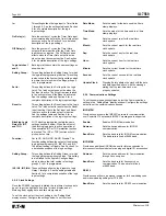
Trigger PF:
This setting is the apparent power factor that the
FP-5000 will trip on.
Reset PF:
This setting is the apparent power factor at which
the FP-5000 will reset the apparent power factor
function. It is like setting a hysterisis for the
Trigger setting.
Delay:
This setting defines the delay (in seconds) that the
Trigger PF must be active before the FP-5000 will
initiate a trip signal.
The Apparent Power Factor is computed by dividing real power
(watts) by volt-amperes. The apparent power factor computation
includes harmonics.
PF
apparent
=
The Displacement Power Factor is computed by dividing the
fundamental watts by the fundamental volt-amperes as shown
below. This definition is only valid at the system fundamental
operating frequency. The Displacement Power Factor isolates
the fundamental portion of the Power Factor from the effects
of harmonics.
watt
(watt
2
+ var
2
)
New values of apparent and displacement power factor are
computed every 32 cycles. The power factor function operates
when the power factor is more lagging than the Trigger PF setting
for the Power Factor Delay setting time. The function resets when
the power factor is more leading than the Reset PF setting for the
Power Factor Delay setting time.
5.5.2.9 Zone Interlocking
Zone Interlocking
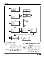
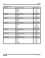
The zone interlocking setting consists of settings to configure a
Zone In and a Zone Out setting. Both Zone In and Zone Out
settings can be set to Disable, Phase, Ground, or Both.
Disable – disables the zone function
Phase – defining the zone function to be a phase signal
Ground – defining the zone function to be a phase signal
Both – defining the zone function to be a phase or ground signal
See Section 8.5 for more information on zone interlocking.
5.5.2.10 Alarms
Protection Alarm Settings
A full set of protection alarm settings complement the protection
elements for overcurrent, over/under voltage, unbalance and over/
under frequency. They are designated as another protection
element, for example 50P-3, and are programmed to the alarm
output relay and alarm LED indication. The settings are similar to
the protection settings described above. These elements may be
used for alarm, tripping or logic functions. Custom programming
of the output relay is required if the desired use is not as an
alarm function.
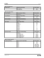
5.5.3 System Alarm Settings
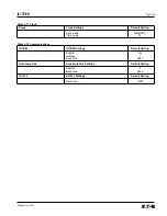
This setting menu contains the settings needed to configure all of
the FP-5000 system alarm functions. Each alarm function can be
disabled. The system alarms are programmed to the alarm output
relay and alarm LED indication. These elements may be used for
alarm, tripping or logic functions. The outputs will need to be
configured if the desired use is not an alarm function. SYSALM
pickup in the Event Log Enable settings must be set to "Yes” to
enable logging of Pickup/ Dropout events related to system alarms.
Watt Power Alarm
Units:
Sets the units for watts measurement
(kW or MW).
Threshold:
Sets the watts threshold level in units
specified, at or above which the power pickup
event occurs. After pickup, if the watts fall
below the specified threshold, a power
dropout event occurs.
Delay (m):
Sets the number of minutes that the watts must
remain at or above threshold, before the
specified trip output occurs.
VAR Power Alarm
Units:
Sets the units for VARS measurement
(kVAR or MVAR).
Threshold:
Sets the VARS threshold level in units
specified, at or above which the power pickup
event occurs. After pickup, if the VARS fall
below the specified threshold, a power
dropout event occurs.
Delay (m):
Sets the number of minutes that the VARS
must remain at or above threshold, before the
specified trip output occurs.
VA Power Alarm
Units:
Sets the units for VA measurement.
(kVA or MVA).
Threshold:
Sets the VA threshold level in units specified,
at or above which the power pickup event
occurs. After pickup, if the VA falls below
the specified threshold, a power dropout
event occurs.
Delay (m):
Sets the number of minutes that the VA must
remain at or above threshold, before the
specified trip output occurs.
Summary of Contents for Cutler-Hammer FP-5000
Page 1: ...IL17569 Effective June 2001 Instructions for FP 5000 Protective Relay...
Page 7: ...IL17569 Table of Contents 6 Effective June 2001 This page left blank intentionally...
Page 13: ...IL17569 Page 2 2 Effective June 2001 Figure 2 2 FP 5000 Simple Wye Connected Application...
Page 14: ...Page 2 3 IL17569 Effective June 2001 Figure 2 3 FP 5000 Simple Open Delta Application...
Page 19: ...IL17569 Page 2 8 Effective June 2001 This page left blank intentionally...
Page 25: ...IL17569 Page 3 6 Effective June 2001 This page left blank intentionally...
Page 98: ...IL17569 Page 5 50 Effective June 2001 This page left blank intentionally...
Page 108: ...IL17569 Page 6 10 Effective June 2001 Figure 6 10 Common Ct Wiring Configurations...
Page 141: ...IL17569 Page 11 4 Effective June 2001 This page left blank intentionally...
Page 165: ...IL17569 Page Appendix 6 Effective June 2001 Figure 13 2 ANSI Very Inverse...
Page 166: ...Page Appendix 7 IL17569 Effective June 2001 Figure 13 3 ANSI Extremely Inverse...
Page 167: ...IL17569 Page Appendix 8 Effective June 2001 Figure 13 4 IEC A Figure 13 4 IEC A...
Page 168: ...Page Appendix 9 IL17569 Effective June 2001 Figure 13 5 IEC B...
Page 169: ...IL17569 Page Appendix 10 Effective June 2001 Figure 13 6 IEC C...
Page 170: ...Page Appendix 11 IL17569 Effective June 2001 Figure 13 7 IEC...
Page 171: ...IL17569 Page Appendix 12 Effective June 2001 Figure 13 8 ANSI...
Page 172: ...Page Appendix 13 IL17569 Effective June 2001 Figure 13 9 Thermal...
Page 173: ...IL17569 Page Appendix 14 Effective June 2001 Figure 13 10 Phase I4 t...
Page 174: ...Page Appendix 15 IL17569 Effective June 2001 Figure 13 11 Phase I2 t...
Page 175: ...IL17569 Page Appendix 16 Effective June 2001 Figure 13 12 Phase It...
Page 176: ...Page Appendix 17 IL17569 Effective June 2001 Figure 13 13 Phase 12 I4 t...
Page 177: ...IL17569 Page Appendix 18 Effective June 2001 Figure 13 14 Phase I2 t...
Page 178: ...Page Appendix 19 IL17569 Effective June 2001 Figure 13 15 Ground IT...
Page 180: ...Page Appendix 21 IL17569 Effective June 2001 This page left blank intentionally...
Page 187: ...Publication No IL17569 June 2001 Pittsburgh Pennsylvania U S A...


