IQ DP-4000
SECTION 5 - PROGRAMMING THE IQ DP-4000
5.1 2. 2
Latched/Unlatched (Auto-reset) Alarm
Setpoint
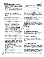
This setpoint allows the IQ DP-4000 to operate in one of
two ways - the latched mode or the unlatched mode.
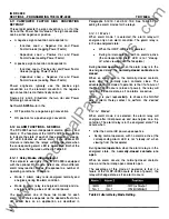
See Table 5.J for setting this option.
•
Latched Mode. I n the latched mode, you can only
reset an active alarm manually (either from the
faceplate, the reset input, or over IMPACC). The
alarm
will not
automatically clear once the reset
conditions are met. If the alarm condition still exists,
you cannot reset the alarm unless you disable it.
•
Unlatched Mode (auto-reset). If an alarm occurs,
the DP-4000 will automatically reset the alarm when
the reset conditions are met, based on the program
settings (for example, reset thresholds and reset
delays). The DP-4000 will not reset if the alarm
condition still exists.
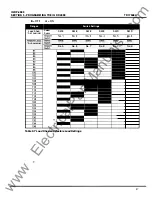
Table
5. J
Latched/Unlatched Settings
5.1 2. 3
Activate on Overvoltage Alarm Setpoint
This setpoint activates the selected alarm on an
overvoltage condition. When enabled, the IQ DP-4000
compares the metered line-to-line voltage of each
phase to the overvoltage detection level (see Section
5. 1 2 . 1 2) , and activates the alarm if the threshold is
exceeded for a time greater than the alarm delay on any
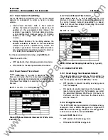
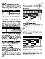
phase (see Section 5. 1 2. 1 0) . See Table 5.K for setting
this option.
Alarm 1
Alarm
2
Position
SW6
No. 3
SW7
No. 3
OFF disables Activate on
ON enables Activate on
Table
5. K
Activate on Overvoltage Settings
5. 1 2.4
Activate on Undervoltage Alarm Setpoint
This setpoint activates the selected alarm on an
undervoltage condition. If enabled, the IQ DP-4000
compares the metered line-to-line voltage of each
phase to the undervoltage detection level (see Section
5. 1 2. 1 3) , and activates the alarm if the metered voltage
is below the threshold for a time greater than the alarm
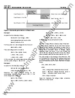
delay on any phase (see Section 5. 1 2. 1 0). See Table
5.L for setting this option.
TD1 7548A
Alarm 1
Alarm 2
Position
SW6
No. 4
SW7
No. 4
OFF disables Activate on
ON enables Activate on
Table 5.L Activate on Undervoltage Settings
5. 1 2.5
Activate on Voltage Phase Loss Alarm
Setpoint
This setpoint activates the selected alarm on a voltage
phase loss condition. A voltage phase loss occurs when
the line-to-line voltage on any phase is less than 50% of
the nominal line voltage.
When this alarm is set, the IQ DP-4000 compares the
metered voltage to 50% of the selected nominal voltage
(see Section 5.5), and activates the alarm if a voltage
phase loss exists for a time greater than the alarm delay
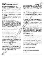
(see Section 5. 1 2. 1 0) . See Table 5.M for setting this
option.
Alarm 1
Alarm 2
Position
SW6
No. 5
SW7
No. 5
OFF disables Activate on
Phase Loss
ON enables Activate on
Phase Loss
Table
5. M
Activate on Voltage Phase Loss Settings
5.1 2. 6
Activate on Voltage Phase Unbalance Alarm
Setpoint
This setpoint activates the alarm on a voltage phase
unbalance condition. The IQ DP-4000 compares the
metered voltage to the voltage phase unbalance
detection level (see Section 5 . 1 2 . 1 4), and activates the
alarm if the maximum deviation between any two
phases of the metered voltage exceeds the threshold
for longer than the alarm delay (see Section 5. 1 2. 1 0).
Table 5.N shows the settings for this option.
Alarm 1
Alarm 2
Position
SW6
No. 6
SW?
No. 6
OFF disables Activate on
Phase Unbalance
ON enables Activate on
Phase Unbalance
Table
5. N
Activate on Voltage Phase Unbalance
Settings
5.1 2. 7
Activate on Voltage Phase Reversal Alarm
Setpoint
This setpoint activates the alarm on a voltage phase
reversal condition. The IQ DP-4000 compares the
27
www
. ElectricalPartManuals
. com


