IQ DP-4000
SECTION 4 - INSTALLATION AND STARTUP
TD 17548B
14
OFF AND LOCKED OUT BEFORE PERFORMING
ANY WORK ON THE IQ DP-4000 OR ITS
ASSOCIATED EQUIPMENT. FAILURE TO OBSERVE
THIS PRACTICE CAN RESULT IN SERIOUS OR
EVEN FATAL INJURY AND/OR EQUIPMENT
DAMAGE.
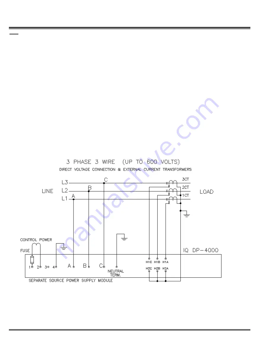
Figures 4.4 - 4.15 show typical wiring plans. When
referring to the figures, note the following:
1. Phasing and polarity of the AC current inputs and
the AC voltage inputs and their relationship are
critical to the correct operation of the wattmeter.
2. The incoming AC line phases A, B, and C connect
from three external potential transformers (PT’s) to
the AC line connection terminals on the chassis
(above 600V).
3. You can use NO and NC contacts from the Relays
to control external devices. These contacts are rated
at 10 amps for 120/240 VAC or 30 VDC.
4. The wires connecting to the IQ DP-4000 must not be
larger than AWG No. 14. Larger wires will not
connect properly with the various terminal blocks.
5. Keep the wiring between the current transformers
and the IQ DP-4000 as short as possible (200 feet
max.). Whenever possible, route these lines away
from other AC lines and inductive devices. If the
lines must cross other AC lines, cross them at right
angles.
6. The protective functions of the IQ DP-4000 (with the
optional I/O module) directly control the Relays, as
described in Section 5.
7. Connect the sync pulse terminals to the dry contact
input only. The 24VDC is supplied by the IQ DP-
4000 on Terminal 1.
Figure 4.4 3-Phase, 3 Wire (up to 600 volts) Wiring Diagram (Separate Source)
Summary of Contents for Cutler-Hammer IQ DP-4000
Page 2: ......


