background image

Effective 7/1/2003

Page 27

I.L. 70C1037H04

   WARNING

PERSONAL INJURY CAN OCCUR WHEN WORKING ON

POWER SYSTEMS. ALWAYS TURN OFF POWER

SUPPLYING BREAKER BEFORE CONDUCTING TESTS.

TEST OUT OF THE CELL, IF POSSIBLE. THERE IS A

HAZARD OF ELECTRICAL SHOCK OR BURN WHEN-

EVER WORKING IN OR AROUND ELECTRICAL EQUIP-

MENT.

Verify the grounding points of the system using high-

voltage testers and resistance bridges to ensure that
ground paths do not exist that could bypass the sensors.

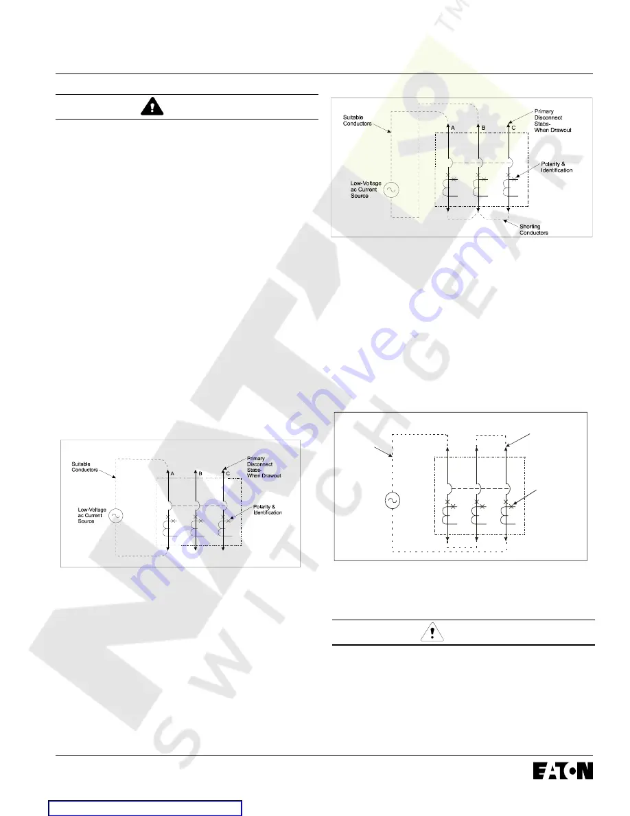
Use a low-voltage (0 to 24 volt), high-current, ac source to

apply a test current of 125 percent of the Digitrip unit pick-

up setting through one phase of the circuit breaker. This

should cause the breaker to trip in less than 1 second and

operate the alarm indicator, if one is supplied. Reset the

breaker and the alarm indicator. Repeat the test on the

other two phases 

(See Figure 5.2).

Apply the same current as described above through one

phase of the breaker, returning through the neutral sensor.

The breaker should not trip, and the alarm indicator, if one

is supplied, should not operate. Repeat the test on the

other two phases.

Figure 5.2 Connection Details for Conducting Single Pole,

Single Phase Current Tests with the Breaker

Removed from the Cell

Apply the same current as described above through any

two phases of the breaker. The breaker should not trip, and

the alarm indicator,


if one is supplied,


should not operate.

Repeat the test using the other two combinations of

breaker phases 

(See Figure 5.3)

 or through a breaker pole

and the neutral that employs a neutral sensor 

.

An alternative test setup is shown in Fig. 5.4. This three

pole  in series hookup should be employed  when a low

Ground Pickup setting is to be tested like 0.24x and 0.3x

and if Aux power  to Digitrip can not be provided. The Test

Circuit does provide a net Residual ground current excita-

tion of “1”. Two of the phases cancel each other out as far

as ground fault but now the Digitrip is provided with three

pole power up  current simulating three phase power.

Figure 5.3 Connection Details for Conducting Single Phase

Current Tests with the Breaker Removed from

the Cell

Suitable

Conductors

Low-Voltage
ac Current

Source

Primary

Disconnect
Stabs-

When Drawout

A

B

C

Polarity &

Identification

Figure 5.4 Alternate Connection Details using three poles

to develope a Ground Fault Condition.

  CAUTION

RESTORE ALL TEMPORARY CONNECTIONS MADE

FOR THE PURPOSE OF CONDUCTING TESTS TO

PROPER OPERATING CONDITIONS BEFORE RETURN-
ING THE BREAKER TO SERVICE.

Record the test results on the test form provided with the

equipment

 (See Figure 8.3).

Courtesy of NationalSwitchgear.com

Summary of Contents for Cutler-Hammer Magnum Digitrip 220+

Page 1: ...9 2 Remote Master Computer 24 4 9 3 INCOM Network Interconnections 24 5 0 Test Procedures 25 5 1 General 25 5 2 When to Test 25 5 3 Functional Field Testing 25 5 3 1 Field Test Kit 25 5 3 2 Handheld...

Page 2: ...d can be replaced or upgraded in the field by the customer This instruction book specifically covers the application of Digitrip Trip Units see Figure 1 1 installed in Magnum and Magnum DS Breakers Th...

Page 3: ...Delay Time I2t at 6 x Ir Protection Long Delay Thermal Memory 0 4 1 0 x In 2 24 Seconds Yes 0 4 1 0 x In 2 24 Seconds Yes 0 4 1 0 x In 2 24 Seconds Yes 0 4 1 0 x In 2 24 Seconds Yes Short Short Delay...

Page 4: ...Alarm NA X X X Remote Messages Trip Long Delay Trip X X X X Short Delay Trip X X X X Instantaneous Trip X X X X Ground Trip NA X NA X Over temperature Trip X X X X Plug Trip plug problem X X X X MCR...

Page 5: ...1 and 520MC CLSI model Fig 3 4 1 can be used on 3 pole or 4 pole circuit breakers for the protection of the neutral circuit Only these four models can provide neutral protec tion although models MLSI...

Page 6: ...e door to release the rating plug from the trip unit To remove the trip unit from the circuit breaker deflect the spring clip to release the unit from the steel mounting plate Pull the unit to disenga...

Page 7: ...splay data until load current reaches approxi mately 30 1 phase or 10 3 phase of the In rating 1 6 2 Ground Alarm A second function of the module is to provide either a ground trip or ground alarm onl...

Page 8: ...hest value that can be presented is 9999 Any fault currents greater than this value will be shown as HI Pushing the Reset pushbutton will clear this data Also related to the phase value after a trip e...

Page 9: ...INJURY Figure 2 1 Tripping Circuit for a Typical Magnum Breaker Partial OBSERVE POLARITY MARKINGS ON THE TRIP AC TUATOR LEADSAND CONNECT THEM PROPERLY USING THE INSTRUCTIONS PROVIDED 2 2 Low Energy Tr...

Page 10: ...ION IF THE SENSOR CONNECTIONSARE INCORRECT A NUISANCE TRIP MAY OCCUR ALWAYS OBSERVE THE POLARITY MARKINGS ON THE INSTALLATION DRAW INGS TO INSURE CORRECT GROUND FAULT EQUIP MENT PERFORMANCE CONDUCT FI...

Page 11: ...ed Processor chip The microcomputer continually digitizes these signals This data is used to calculate true RMS current values which are then continually compared with the protection function settings...

Page 12: ...1 3 3 2 2 1 1 K2 8 B 4 Load Notes B 6 K1 4 K1 3 10 1 10 1 AUX CT K2 9 K2 1 K2 7 B 5 B 7 K1 5 K1 2 Black Trip Actuator LB LC LA K1 6 K1 7 K1 8 K1 9 1 1 1 Source Load K2 8 K2 9 B 4 B 6 20 1 AUX CTs 20 1...

Page 13: ...at the PC board donut transformer to sense ground fault via element R 5 Do not jumper on secondary contacts B 6 B 7 This will defeat all ground fault protection in application for 4 pole breaker Grou...

Page 14: ...Effective 7 1 2003 Page 14 I L 70C1037H04 Figure 2 6 Source Ground Fault Sensing Scheme for 3200A Frame Figure 2 7 Source Ground Fault Sensing Scheme for 4000A Frame Courtesy of NationalSwitchgear com...

Page 15: ...N N Digitrip Ground Sensor Breaker M2 trips since this is the only breaker seeing the I fault via element R No jumper on B 6 B 7 terminals all breakers are programmed for standard Residual Ground Faul...

Page 16: ...o cycles following an initial circuit breaker closing operation The Making Current Release will trip the circuit breaker instantaneously and flash the Instantaneous LED 3 4 Zone Interlocking 520 famil...

Page 17: ...See Section 3 3 Trip Actuator LED Pulse Circuit Battery 3V Ground Alarm Power Supply Optional for 520M Required for 520MC FET Trip See Section 1 2 Trip LED Rating Plug Integrated Processor C ip H TM...

Page 18: ...Effective 7 1 2003 Page 18 I L 70C1037H04 Figure 3 2 1 Digitrip 220 PLI Figure 3 2 3 Digitrip 520 LSIG Figure 3 2 2 Digitrip 520 LSI Figure 3 2 4 Digitrip 520i WLSIG Courtesy of NationalSwitchgear com...

Page 19: ...tive 7 1 2003 Page 19 I L 70C1037H04 Figure 3 3 1 Digitrip 520M MLSI Figure 3 3 3 Digitrip 520M MLSIG Figure 3 3 2 Digitrip 520M MLSIA Figure 3 3 4 Digitrip 520Mi MWLSIG Courtesy of NationalSwitchgear...

Page 20: ...ive 7 1 2003 Page 20 I L 70C1037H04 Figure 3 4 1 Digitrip 520MC CLSI Figure 3 4 2 Digitrip 520MC CLSIA Figure 3 4 3 Digitrip 520MC CLSIG Figure 3 4 4 Digitrip 520MC CWLSIG Courtesy of NationalSwitchge...

Page 21: ...S 4 1 General Before placing any circuit breaker in operation set each trip unit protection setting to the values specified by the engineer responsible for the installation The number of settings that...

Page 22: ...er The action of the LTM must be considered when performing multiple Long Delay Time tests See Section 5 4 4 4 Short Delay Current Setting There are 8 available Short Delay Current Settings as illustr...

Page 23: ...Settings 4 9 INCOM Digitrip 520MC Models only INCOM communication to a host computer or a BIM is possible with the Digitrip 520MC unit The address range is 001 through 999 The factory default address...

Page 24: ...e it and display it in a useful manner Following an over current trip operation the sequence of coded data varies slightly The cause of trip the value the phase or ground current responsible for the t...

Page 25: ...he Magnum Test KitAdapter 8779C02G04 can be used to test the trip unit and breaker 5 0 TEST PROCEDURES 5 1 General WARNING DO NOT ATTEMPT TO INSTALL TEST OR PERFORM MAINTENANCE ON EQUIPMENT WHILE IT I...

Page 26: ...rd in the Test Kit and serve to power up the display on the 520M trip unit LED s A and B function to represent sufficient battery voltage from both the single Lithium cell and the six Alkaline batteri...

Page 27: ...ved from the Cell Apply the same current as described above through any two phases of the breaker The breaker should not trip and the alarm indicator if one is supplied should not operate Repeat the t...

Page 28: ...d then replace battery See Figure 6 1 This will activate the battery Check the battery status by depressing the battery test pushbutton 6 2 Battery Check The battery is a long life lithium camera type...

Page 29: ...tion of the protection function of the breaker without affecting its short circuit current capability For the Digitrip 520 family of trip units this is implemented by changing the current sensors and...

Page 30: ...TTINGS Circuit No Address Breaker Shop Order Reference PER UNIT MULTIPLIERS Rating Plug Amperes In Ir Continuous Ampere Rating LDS x In Trip Function Per Unit Setting Multi Ampere Equivalent Setting T...

Page 31: ...uit No Address Breaker Shop Order Reference Settings Reference Trip Function Orig 0 Rev 1 Rev 2 Rev 3 Instantaneous Long Delay Setting Long Delay Time Short Setting Short Time Ground Fault Setting Gro...

Page 32: ...orm GROUND FAULT TEST RECORD FORM Ground Fault Test Record should be retained by those in charge of the building s electrical installation in order to be available to the authority having jurisdiction...

Page 33: ...to the feeder trip unit the feeder will send a restraint interlocking signal to Z1 Main and feeder trip units will begin to time out and in the event that the branch breaker does not clear the fault t...

Page 34: ...m power conductors DO NOT GROUND any Zone Interlocking wiring The maximum distance between two farthest breakers on different zones from the ZO downstream to ZI upstream terminals is 250 feet 76m A ma...

Page 35: ...lfunctioning Replace trip unit There actually is a ground fault Find location of the fault On 4 wire residual systems the neutral current sensor may not have the correct ratio or be properly connected...

Page 36: ...ently adding Aux Power and then depress Reset pushbutton to fully clear trip buffer See also Note in Section 5 3 2 2 Light load Check breaker ordering information Refer to Sections 1 6 and 1 6 1 LCD D...

Page 37: ...Effective 7 1 2003 Page 37 I L 70C1037H04 Appendix C Typical Breaker Master Connection Diagram Courtesy of NationalSwitchgear com...

Page 38: ...mon and SHielD Three Baud rates of 1200 9600 or 19200 are selectable via programming switch for the MODBUS network The INCOM Baud rate is fixed at 9600 Baud B 2 B 1 1 Magnum Breaker 2 B 2 B 1 Magnum B...

Page 39: ...RRANTIES EXPRESSED OR IMPLIED INCLUD ING WARRANTIES OF FITNESS FORAPARTICULAR PURPOSE OR MERCHANTABILITY OR WARRANTIES ARISING FROM THE COURSE OF DEALING OR US AGE OF TRADE ARE MADE REGARDING THE INFO...

Page 40: ...Effective 7 1 2003 Page 40 I L 70C1037H04 Cutler Hammer Pittsburgh PAU S A Effective 7 1 2003 Printed in U S A Courtesy of NationalSwitchgear com...

Reviews: