background image

Intelligent Technologies (

IT.

) D77A I/O Module Products

MN05002001E 

For more information visit: www.EatonElectrical.com

37

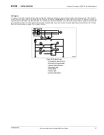
AC Inputs

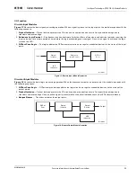
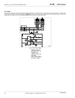
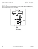
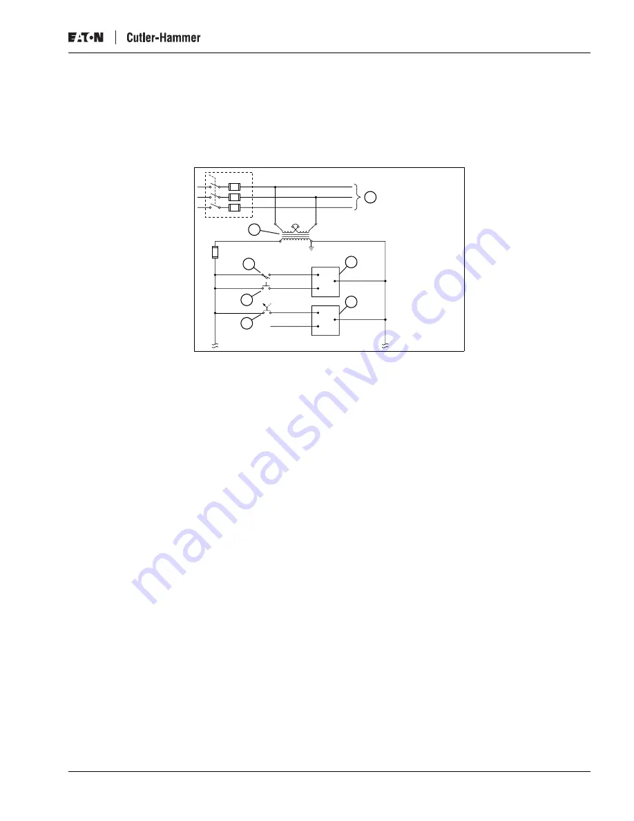
AC power is typically used to energize loads related to machinery function such as solenoid valves and motor starters. The same AC 
power source is often used as signal power for inputs as illustrated in 

Figure 35

. The input devices to which AC inputs are wired are 

typically two-lead devices like push buttons, limit switches and selector switches. One side of the input device is wired to an AC power 
source while the other is wired to the input terminal. Another input terminal is wired to a grounded neutral wire. Refer to 

AC Output 

Module Specifications on page 13

 for module details.

Figure 35: AC Input Wiring

a) Three-phase Motor Circuits
b) First Point of Input Module
c) Second Point of Module 
d) Selector Switch
e) Push Button
f) Limit Switch
g) Control Transformer

f

g

a

b

c

d

e

L1

1FU

L2

X1

X2

0

C0

C1

1

2

3

2FU

L3

10FU

L1

L2

N/C

3FU

H1

H4

H3

H2

JIC-0002

Summary of Contents for D77A

Page 1: ...chnologies IT D77A I O Module Products Installation and User Manual November 2006 Supersedes October 2005 Part Numbers D77A DI8 D77A RQ8 D77A DI16 D77A RQ16 D77A DQ8 D77A DI8DQ8 D77A DQ16 D77A DI8RQ8 D77A AI8 D77A AI8AQ8 D77A AI16 D77A AI8RQ8 D77A AQ8 D77A NI4 D77A AQ16 D77A NQ2 ...

Page 2: ......
Page 3: ...REGARDING THE INFORMATION RECOMMENDATIONS AND DESCRIPTIONS CONTAINED HEREIN In no event will Eaton Electrical Inc be responsible to the purchaser or user in contract in tort including negligence strict liability or otherwise for any special indirect incidental or consequential damage or loss whatsoever including but not limited to damage or loss of use of equipment plant or power system cost of ca...

Page 4: ...Suppression 5 Environmental Specifications 6 Device Default I O Data 6 I O Module Summary 7 Input Specifications 8 Output Specifications 13 Special I O Specifications 18 THEORY OF OPERATION 22 Out of box Default Operation 22 Typical Application 22 I O Function 23 INSTALLATION 27 Setting Group ID 27 QCPort Connections 32 Configuration 34 Field Wiring 35 TROUBLESHOOTING AND MAINTENANCE 45 Status LED...

Page 5: ...ail Locking Tab 29 Figure 26 Removable Terminal Locking Tab 29 Figure 27 Removable Terminal Locking Tabs 30 Figure 28 Unlock DIN Rail Locking Tab 30 Figure 29 Lock DIN Rail Locking Tab 31 Figure 30 Removable Terminal Locking Tab 31 Figure 31 QCPort Backplane Interconnect 32 Figure 32 QCPort Interconnect Backplane Connectors 32 Figure 33 QCPort Connector 33 Figure 34 I O Property Page 34 Figure 35 ...

Page 6: ...tatus Available in I O As Control Elements 49 Table 41 0x006F 111 16 bit Signed Analog Input Data Available in I O As Control Elements 49 Table 42 0x0070 112 16 bit Signed Analog Output Data Available in I O As Control Elements 49 Table 43 0x8001 32769 Device Identity 50 Table 44 0x8002 32770 Configuration CRC 50 Table 45 0x8003 32771 Node ID 50 Table 46 0x8004 32772 Operating Mode 50 Table 47 0x8...

Page 7: ...te peligrosa que si no es evitada podrá resultar en heridas corporales menores o moderadas o en serios daños al producto La situación descrita en la PRECAUCIÓN podrá causar serios resultados si no es evitada Medidas importantes de seguridad son descritas en la PRECAUCIÓN como también en la ADVERTENCIA WARNING AVERTISSEMENT ADVERTENCIA Some control equipment and electronic controllers are connected...

Page 8: ...Antes de comenzar la instalación configuración o la operación lea y comprenda el manual completo WARNING AVERTISSEMENT ADVERTENCIA Hazardous voltage can cause electric shock and burns Always disconnect power before proceeding with any work on this product La tension dangereuse peut causer des électrochocs et des brûlures Coupez toujours le courant avant d entreprendre tout travail sur ce produit L...

Page 9: ... for Pollution Degree 2 environments clean and dry Component Characteristics This section identifies special features engineered into the Cutler Hammer IT D77A I O modules All Modules The IT D77A I O modules have the following common features LED Status When the LED is illuminated the proper ON state signal is received at the input or at the output point Removable Lockable Terminals Terminals are ...

Page 10: ...hannels Each analog channel has two analog output channels Type Selection Each module can be set as a voltage output or a current loop output Approval Certifications Table 1 Approvals Certifications Standard Approval Certifications Agency Certifications UL 508 CE Low Voltage Directive ATEX Directive CUL CSA C22 2 No 14 Radiated and Conducted Emissions EN 5011 Class A Electrical EMC ESD Immunity IE...

Page 11: ...he first four positions in the first group indicate the product family The next two places in the second group indicate the I O type The third group uses one or two places to indicate the number of points in the module The last group is used only for combination modules Table 2 Catalog Numbering System Product Line Prefix D77A I O Module Products A AC D DC R Relay N Analog I O Type Number of Point...

Page 12: ...mponent Location a Number of points b Terminal Blocks Removable c DIN Rail Locking Tab d D77 Part Number e QC Port Backplane Connector f I O Status LED g Group ID Selector Switch Address h Status LED i I O Type I for Input Q for Output j Voltage AC DC Relay Analog 0 2 4 8 6 10 12 14 0 2 4 8 6 10 12 14 I 24V 8 Pt I 24V 8 Pt 0 1 1 C0 0 C0 3 2 C1 2 3 C1 4 5 C2 4 5 C2 6 7 C3 6 7 C3 0 1 C0 2 3 C1 4 5 C...

Page 13: ...ype When specifying the 24 volt DC power supply the power rating must support the sum of all the modules current draw added to the system power requirements For more information on the sizing of power supplies refer to the IT QCPort System Install and Planning Guide Publication No MN05001002E Surge Suppression IT D77A Discrete I O output modules have built in surge suppression snubbers to reduce t...

Page 14: ...nsing Altitude Above 2000 meters 6600 feet consult factory Shock IEC 68 2 27 15G any direction for 11 milliseconds Relay Operation 8G any direction Vibration IEC 68 2 6 5 150 Hz 5G 0 7 mm maximum peak to peak Relay Operation 10 55 Hz 3G 0 7 mm maximum peak to peak Pollution Degree Devices are intended to be installed in a pollution degree 2 environment Bit 7 Bit 6 Bit 5 Bit 4 Bit 3 Bit 2 Bit 1 Bit...

Page 15: ...ule Page 13 D77A AQ16 120V AC Output AC Output Module Page 13 DC D77A DI8 24V DC Input DC Input Module Page 9 D77A DI16 24V DC Input DC Input Module Page 9 D77A DQ8 24V DC Output DC Sink Output Module Page 14 D77A DQ16 24V DC Output DC Sink Output Module Page 14 Relay D77A RQ8 0 30V DC Output Relay Output Module Page 15 0 125V AC D77A RQ16 0 30V DC Output Relay Output Module Page 15 0 125V AC Comb...

Page 16: ...50 60 Hz 120V AC 50 60 Hz Operating Voltage 80 140V AC 50 60 Hz 80 140V AC 50 60 Hz Number of Inputs 8 16 Points per Common 2 2 OFF State Voltage 0 30V AC 0 30V AC ON State Voltage 80V AC 140V AC 80V AC 140V AC Nominal Input Current 15 mA 15 mA Signal Delay 8 33 ms 60 Hz 10 ms 50 Hz 8 33 ms 60 Hz 10 ms 50 Hz QCPort Current Draw 33 mA 46 mA Isolation 1 5kV 1 5kV Terminal Screw Torque 4 5 inch pound...

Page 17: ...Sink Source Sink Source Nominal Input Voltage 24V DC 24V DC Operating Voltage 18 30V DC 18 30V DC Number of Inputs 8 16 Points per Common 2 2 Signal Delay 5 ms 5 ms OFF State Voltage 0 6V DC 0 6V DC ON State Voltage 18V 30V DC 18V 30V DC Nominal Input Current 5 mA 5 mA QCPort Current Draw 35 mA 63 mA Isolation 1 5kV 1 5kV Terminal Screw Torque 4 5 inch pounds 0 51 Newton meters 4 5 inch pounds 0 5...

Page 18: ...14 bit 0 20mA 14 bit 0 10VDC 14 bit 4 20mA 14 bit 1 5VDC 14 bit 250Hz 0 5VDC 14 bit 0 20mA 12 bit 0 10VDC 13 bit 4 20mA 12 bit 1 5VDC 12 bit 500Hz 0 5VDC 9 bit 0 20mA 9 bit 0 10VDC 10 bit 4 20mA 9 bit 1 5VDC 9 bit Input Full Scale Range 0 10 5V or 0 5 25V 0 21 mA Maximum Overload at Input Terminal 30VDC 32 mA Number of Channels 4 Selectable Input Filter Frequency 50Hz 60Hz 250Hz 500Hz Input Group ...

Page 19: ...lectrical com 11 Figure 5 D77A NI4 Analog Input Module Diagrams a D77A NI4 Voltage Input Channels b D77A NI4 Current Input Channels See D77A NI4 Analog Input Module Specifications on page 10 V0 I0 C0 V1 I1 C1 V2 I2 C2 V3 I3 C3 V0 I0 C0 V1 I1 C1 V2 I2 C2 V3 I3 C3 JIC 0013 a b NC NC NC NC I I I I V V V V ...

Page 20: ... 20mA Range Setting e 4 20mA Range Setting 14 Bit Resolution Equations Vdc Voltage input value mA Current input value N Decimal value 0 5 Vdc 1 5 Vdc Vdc 1 6241 2 x N 0 10 Vdc Vdc 1 3120 6 x N 4 20 mA 0 20 mA mA 1 1560 2 x N 5 25V 5V 0V 0 32766 31206 21mA 20mA 0mA 0 5 25V 5V 0V 0 32766 31206 32766 31206 10 5V 10V 0V 0 1V 0 5V 6242 3120 21mA 20mA 0mA 0 32766 31206 32766 31206 4mA 6242 4992 A D E B ...

Page 21: ...ts per Common 2 2 Minimum Load Current Resistive 15 mA 15 mA Max Current Point Resistive 5A 30 C 1A 55 C 5A 30 C 1A 55 C Max Current Module Resistive 4A 30 C 8A 0 55 C 8A 30 C 1 6A 0 55 C Surge Current 10 ms 10A 10A OFF State Leakage 2 mA 2 mA Signal Delay 8 33 ms 60 Hz 10 ms 50 Hz 8 33 ms 60 Hz 10 ms 50 Hz QCPort Current Draw 120 mA 220 mA Isolation 1 5kV 1 5kV Terminal Screw Torque 4 5 inch poun...

Page 22: ...4V DC 24V DC Operating Voltage 18 30V DC 18 30V DC Number of Inputs 8 16 Points per Common 4 4 Signal Delay 1 ms 1 ms Max Current Point 0 75A 0 75A Max Current Module Resistive 6A 12A Surge Current 10 ms 4A 4A OFF State Leakage 1 mA 1 mA QCPort Current Draw 85 mA 126 mA Isolation 1 5kV 1 5kV Terminal Screw Torque 4 5 inch pounds 0 51 Newton meters 4 5 inch pounds 0 51 Newton meters 24 OUT OUT C CR...

Page 23: ...lay OFF Time 6 ms 6 ms Relay ON Time 3 ms 3 ms Max Current Point Resistive 3 A 3 A Max Current Module Resistive 24 A 48 A Electrical Life 100 000 Cycles 100 000 Cycles Mechanical Life 1 000 000 Cycles 1 000 000 Cycles QCPort Current Draw 92 mA 164 mA Isolation 1 5 kV 1 5 kV Terminal Screw Torque 4 5 inch pounds 0 51 Newton meters 4 5 inch pounds 0 51 Newton meters OUT OUT C CR CR V A C DC V A C DC...

Page 24: ...t Resolution 0 5VDC 13bit 0 20mA 14 bit 0 10VDC 14 bit 4 20mA 14 bit 1 5VDC 13 bit Output Full Scale Range 0 10 5V or 0 5 25V 0 21 mA Maximum Overload at Input Terminal 36V DC Number of Channels 2 Resistive Load Less than 500 ohms Load Range Greater than 1k ohm Maximum Inductive Load 0 1 mH Maximum Capacitive Load 1 µF Accuracy 0 8 Full Scale 25 C 1 0 Full Scale 0 55 C Update Rate 350 NS Output Im...

Page 25: ... Setting d 0 20mA Range Setting e 4 20mA Range Setting 14 Bit Resolution Equations Vdc Voltage input value mA Current input value N Decimal value 0 5 Vdc 1 5 Vdc Vdc 1 6241 2 x N 0 10 Vdc Vdc 1 3120 6 x N 4 20 mA 0 20 mA mA 1 1560 2 x N 5 25V 5V 0V 0 32766 31206 21mA 20mA 0mA 0 5 25V 5V 0V 0 32766 31206 32766 31206 10 5V 10V 0V 0 1V 0 5V 6242 3120 21mA 20mA 0mA 0 32766 31206 32766 31206 4mA 6242 4...

Page 26: ... DI8DQ8 DC Sink Source Input DC MOSFET Sink Output Nominal Voltage 24V DC 24V DC Operating Voltage 18 30V DC 18 30V DC Number of Points 8 8 Points per Common 2 2 Signal Delay 5 ms OFF State Voltage 0 6V DC ON State Voltage 18V 30V DC Nominal Current 5 mA Signal Delay 1 ms Max Current Point Resistive 0 75A Max Current Module Resistive 6A Surge Current 10 ms 4A OFF State Leakage 1 mA QCPort Current ...

Page 27: ...rating Voltage 18 30V DC 0 140V AC 0 30V DC Number of Points 8 8 Points per Common 2 2 Signal Delay 5 ms OFF State Voltage 0 6V DC ON State Voltage 18V 30V DC Nominal Current 5 mA Signal Delay Relay ON Time 3 ms Relay OFF Time 6 ms Max Current Point Resistive 3A Max Current Module Resistive 24A Mechanical Life 1 000 000 Operations Electrical Life 100 000 Operations QCPort Current Draw 121 mA Isola...

Page 28: ...V AC 50 60 Hz Operating Voltage 80 140V AC 80 140 V AC Number of Points 8 8 Points per Common 2 2 OFF State Voltage 0 30V AC ON State Voltage 80V 140V AC Minimal Load Current Resistive 15 mA Signal Delay 8 33 ms 60 Hz 10 ms 50 Hz Max Current Point Resistive 0 5A 30 C 0 1A 55 C Max Current Module Resistive 4A 30 C 0 8A 55 C Surge Current 10 ms 10A OFF State Leakage 2 mA QCPort Current Draw 132 mA I...

Page 29: ... 140V AC 0 140V AC 0 30V DC Number of Points 8 8 Points per Common 2 2 Signal Delay 5 ms OFF State Voltage 0 80V AC ON State Voltage 180V 140V AC Maximum Load Current Resistive 15 mA Signal Delay 8 33 ms 60 Hz 10 ms 50 Hz Relay ON Time 3 ms Relay OFF Time 6 ms Max Current Point Resistive 3A Max Current Module Resistive 24A Mechanical Life 1 000 000 Operations Electrical Life 100 000 Operations QCP...

Page 30: ...les are properly installed and each has a properly configured Group ID address no additional configuration is needed for standard operation To customize the configuration refer to Configuration on page 34 After customizing the configuration the system can be restored to the default out of box configuration without a software tool such as CH Studio by following these steps 1 Using a screwdriver rot...

Page 31: ... logic updates the QCPort communication on a regular scheduled basis as to the status of the input point Figure 17 Discrete Input Module Operation Discrete Output Modules Figure 18 illustrates the basic logic processing operation When the processor activates an output point the module responds with the following sequence 1 QCPort Com Logic QCPort communication updates the logic circuit on a regula...

Page 32: ...ave the properties of both input and output points in a single module The behavior of the combination module s input and output points are the same as those found in discrete input and output modules Figure 19 Discrete Combination Module Operation D77A 032 Optical Isolation Input Debounce Logic Control Optical Isolation Output Drivers LED Indication Output QCPort Comm ...

Page 33: ...verts it to a digital value This digital value is presented to the controller s central processes unit CPU This data is then presented to the QCPort for external processing Figure 20 Analog Input Module Operation Analog input signal delays are associated with multiplexer switching channel updating and channel reconfiguration These delays are all influenced by analog input filter frequency selectio...

Page 34: ...l data from external sources are extracted from the QCPort and transferred to the controller s central processor unit CPU The digital data from the CPU is transferred to the digital to analog converters DAC The DAC system converts the digital values to linear signals and provides them to the output terminals Figure 21 Analog Output Module Operation V0 I0 QC Port CPU DAC SCHEM 002 V1 I1 DAC P S C0 ...

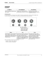
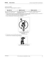
Page 35: ...as heridas corporales o en la muerte Notice Avis Aviso In the examples above the left module has a Group ID of 3 and the right a Group ID of 10 The arrow indicates the Group ID setting not the line Refer to the IT QCPort System Install and Planning Guide Publication No MN05001002E for more information on setting the Group ID Dans les exemples ci dessus le module de gauche porte un numéro d identif...

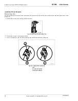
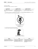
Page 36: ...he front of the device Remove the terminal to gain access to the locking tab 1 Remove the terminal by unlocking the terminal tabs Figure 23 Removable Terminal Locking Tabs 2 Remove the terminal strip from the module 3 Insert a screwdriver under the DIN rail locking tab and lift up to unlock the locking tab Figure 24 Unlock DIN Rail Locking Tab a Tab b Locking Tab Captured c Locking Tab Released D7...

Page 37: ...IÓN Do no rock the module onto the DIN rail The rocking action could damage the module Ne basculez pas le module sur le rail DIN L action de basculement pourrait endommager le module No meza el módulo sobre el riel DIN El mecerlo podrá dañar el módulo Notice Avis Aviso After the strip is installed install interconnects see the IT QCPort System Install and Planning Guide Publication No MN05001002E ...

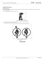
Page 38: ...nt of the device The terminal must be removed to gain access to the locking tab 1 To remove the terminal unlock the terminal tabs Figure 27 Removable Terminal Locking Tabs 2 Remove the terminal strip from the module 3 Insert a screwdriver under the DIN rail locking tab and lift up to unlock the locking tab Figure 28 Unlock DIN Rail Locking Tab a Tab b Locking Tab Captured c Locking Tab Released D7...

Page 39: ...he DIN rail and backplane connector 3 Depress the locking tab to secure the module to the DIN rail Figure 29 Lock DIN Rail Locking Tab a Locking Tab b Locking Tab Captured 4 Install the terminal strip on the front of the module 5 Lock the terminal strip into place using the locking tabs Figure 30 Removable Terminal Locking Tab CAUTION PRÉCAUTION PRECAUCIÓN Do not rock the module onto the DIN rail ...

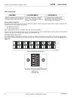
Page 40: ...ct The QCPort backplane interconnect is used when connecting the Adapter and I O modules on a DIN rail The interconnect fits inside the channel of the DIN rail and provides for connection to power and communication to the Adapter and I O products Figure 31 and Figure 32 Figure 31 QCPort Backplane Interconnect Figure 32 QCPort Interconnect Backplane Connectors a Module Side b Backplane Side WARNING...

Page 41: ...ables There are standard sizes for the QCPort Interconnect cables These sizes are listed in the Renewal Parts portion of Troubleshooting and Maintenance Note The maximum current allowed through a QCPort interconnect cable is 1 Amp The maximum number of modules that may be daisy chained together using QCPort interconnect cables is calculated by adding the current rating of each device and keeping t...

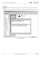
Page 42: ...001E Configuration There are parameters associated with the D77A I O products that can be set using a software tool such as CH Studio for enhanced functionality All of the enhanced features are selectable through CH Studio either in the Property Window or the Property Pages of the device Figure 34 I O Property Page ...

Page 43: ...ez toujours le courant avant d entreprendre tout travail sur ce produit Los voltajes peligrosos pueden causar electrochoque y quemaduras Siempre desconecte la energía antes de proceder con cualquier trabajo en este producto WARNING AVERTISSEMENT ADVERTENCIA Only apply 24V DC to the I O module power terminals Use of any other voltage may result in personal injury property damage and damage to the I...

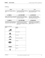
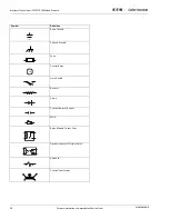
Page 44: ...e information visit www EatonElectrical com MN05002001E Earth Ground Chassis Ground Fuse Control Relay Limit Switch Resistor Diode Contact normally open MOV Relay Module Output Point Optical Isolator AC Output Point Solenoid Control Transformer Symbol Definition CR ...

Page 45: ...re typically two lead devices like push buttons limit switches and selector switches One side of the input device is wired to an AC power source while the other is wired to the input terminal Another input terminal is wired to a grounded neutral wire Refer to AC Output Module Specifications on page 13 for module details Figure 35 AC Input Wiring a Three phase Motor Circuits b First Point of Input ...

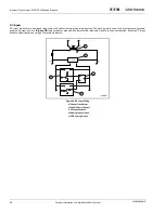
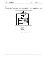
Page 46: ...ypically used with proximity sensors and other solid state devices Figure 36 Input modules may need to be installed relatively close to the sensor location Refer to DC Input Module Specifications on page 9 for module details Figure 36 DC Input Wiring a Control Transformer b 24 VDC Power Supply c DC Input Module d Sinking Input Device e DC Sourcing Device H1 H4 H3 H2 24VDC 10FU C0 0 1 X1 X2 120VAC ...

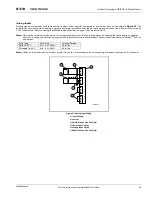
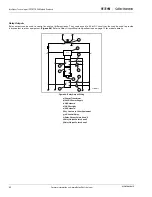
Page 47: ...eld on one end only It is recommended to limit the cable impedance by keeping the cable length as short as possible Limiting the distance from ground to the shield is also recommended The recommended cable is a BeldenTM 8761 or equivalent Note When an input channel in not used jumper from V to C eliminating noise from causing erroneous readings for that channel Figure 37 Analog Input Wiring a Inpu...

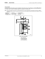
Page 48: ... Figure 38 One side is wired to a grounded neutral wire while the other is wired to the output terminal Refer to AC Output Module Specifications on page 13 for module details Figure 38 AC Output Wiring a Control Transformer b M1 Motor Starter Coil c Solenoid Valve d M2 Motor Starter Coil e Pilot Light f Second Point of Module g First Point of Module d a b c e f g L1 1FU L2 2FU L3 L1 L2 3FU H1 H4 M...

Page 49: ...ourcing signals to other equipment These devices are generally two lead devices as illustrated in Figure 39 Refer to DC Output Module Specifications on page 14 for module details Figure 39 DC Output Wiring a Control Transformer b 24 VDC Power Supply c Solenoid d Pilot Light e Control Relay 1 f Control Relay 2 g DC Output Module Points 2 and 3 h DC Output Module Points 0 and 1 H1 H4 H3 H2 24VDC 10F...

Page 50: ...ntact to other equipment Figure 40 Refer to Relay Output Module Specifications on page 15 for module details Figure 40 Relay Output Wiring a Control Transformer b 24 VDC Power Supply c DC Solenoid d DC Pilot Light e AC Solenoid f Dry Contact to Other Equipment g AC Control Relay h Relay Output Points 4 and 5 i Relay Output Points 2 and 3 j Relay Output Points 0 and 1 H1 H4 H3 H2 24VDC 10FU X1 X2 1...

Page 51: ...cifications on page 16 for module details Note Ground the shield on one end only It is recommended to limit the cable impedance by keeping the cable length as short as possible Limiting the distance from ground to the shield is also recommended The recommended cable is a BeldenTM 8761 or equivalent Figure 41 Analog Output Wiring a Control Transformer b 24 VDC Power Supply c Voltage Output Device d...

Page 52: ...igure 42 illustrates a typical dual purpose module application The advantage is improved I O density and greater flexibility for many applications Refer to Combination Module Specifications on page 18 for module details Figure 42 Combination I O Wiring a Control Transformer b DC Loads c Output Points d Inputs e 24 VDC Power Supply H1 H4 H3 H2 G A B R 24VDC 10FU 0 1 0 C0 1 2 3 LS1 PB1 X1 X2 120VAC ...

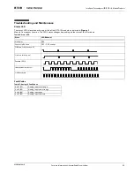
Page 53: ... Figure 1 Module Component Location The LED s status changes depending on the state of the I O module Table 26 Status LED Fault Codes Table 27 Analog 10 Fault Codes State LED Behavior No Power OFF Power Up Routine OFF CRC corrupt Off Line OK mostly off On Line mostly on Faulted 50 Identify device burst Undiscovered 0 x 41 65 Analog input over range 0 x 42 66 Analog input under range 0 x 44 68 Anal...

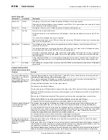
Page 54: ...e parameters are different or the product is different An out of box device was inserted into an actively scanning QCPort power will need to be cycled on QCPort to be accepted While On Line with CH Studio the I O Module disappears It may be that the controller is not allowing enough time for the CH Studio messages and the connection between CH Studio and the Network Adapter is timing out You may h...

Page 55: ...here may be a damaged I O Module or a shorted QCPort communication wire that is prohibiting QCPort communications Remove all the I O Modules from the QCPort system Unplug the Network Adapter from the industrial network Cycle power to the Network Adapter One by one plug the I O Modules back in and verify that the status LED is mostly off as they are plugged back in When the I O Module the causes th...

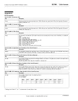
Page 56: ...ed below 0x00 No QCPort Fault 0x01 Node ID Conflict 0x02 Invalid Node ID in Master Slave 0x03 Physical Node ID does not match actual ID 0x04 Duplicate configured nodes online 0x05 Dynamic Node ID overflow 0x06 Invalid baud rate selected 0x07 Errant Device fault 0x08 Problem with data in non volatile memory Size Description 2 Bytes This parameter indicates the application status of the QCPort devic...

Page 57: ...tes This provides channel status for the analog outputs U Under Range O Over Range Size Description Word This provides the 16 bit signed analog input data for the module Size Description Word This provides the 16 bit signed analog output data for the module Byte Bit 7 Bit 6 Bit 5 Bit 4 Bit 3 Bit 2 Bit 1 Bit 0 0 O1 U1 O0 U0 Word Bit Position 15 14 13 12 11 10 9 8 7 6 5 4 3 2 1 0 0 SB Analog Input D...

Page 58: ...r revision must be reported in the LSB Size Description 2 bytes Used for confirmation of a device s configuration Normally the initial values of selected configuration parameters would be included in the calculation The product instruction leaflet should describe which parameters are actually included To facilitate node replacement Device Identity information should not be included in this calcula...

Page 59: ...lue to which the consumption timer is set whenever there is a set of the current value of any parameter on the consumption list Expiration of this interval causes the module to execute communications loss behavior A value of 0 disables this timer Size Description 92 bytes This read only list specifies the n QCPort Parameters that a device supports Size Description 2 bytes This 2n byte read only li...

Page 60: ...e node ID field is 0 all set parameters to the node will be accepted If the node ID field is not 0 set parameter commands to the node will only be accepted from the device having the same node ID as that contained in this parameter Note that if the node ID is set to zero at the same time that a non zero value is loaded to the timer the timer will not decrement Size Description The n bytes Used in ...

Page 61: ...pies of these and other publications please visit our website at www EatonElectrical com Size Description 4 bytes read only Serial number of module Size Description 2 bytes read only Hardware version of module Size Description 2 bytes read only Filter setting of analog input channel 0 50 Hz 1 60 Hz 2 250 Hz 3 500 Hz Publication Description MN05002001E IT D77A I O Module Products Installation and U...

Page 62: ...werware Durant Heinemann Holec and MEM which globally serve the changing needs of the industrial utility light commercial residential and OEM markets For more information visit www EatonElectrical com Eaton Corporation is a diversified industrial manufacturer with 2004 sales of 9 8 billion Eaton is a global leader in electrical systems and components for power quality distribution and control flui...

Reviews: