background image

4

The horn – DB3B UL

   TM261   April 2020   www.eaton.com

The horn – DB3B UL

English

DC version – Up to 3 stage with or without mon-

itoring (alternative configuration) wiring details 

(Type 6)

ote: 

N

This alternative configuration must be specified 

when ordering the unit.

This type can be connected either as a three stage 

common –ve configuration, or if an optional EOL is 

specified if can be configured as a dual stage common 

–ve system with monitoring.

•  4-wire system (Triple stage, ve):

 Connect 

4 supply wires to the terminals as detailed in the 

wiring diagram (1 ve wire and 3 -ve wires). 

Stage 1 is produced when power is applied across the 

ve and stage 1 -ve terminals. Stage 2 is 

produced when power is applied across the common 

+ve and stage 2 -ve terminals. Stage 3 is produced 

when power is applied across the ve and 

stage 3 -ve terminals.

•  4-wire system (Dual stage, common –ve with 

monitoring):

 Connect 4 supply wires to the terminals 

as detailed in the wiring diagram. Stage 1 is produced 

when power is applied across the common -ve and 

stage 1 +ve terminals. Stage 2 is produced when 

power is applied across the common -ve and stage 2 

+ve terminals.


Monitoring functionality is obtained when the supply is 

connected across M1 & M2 terminals. 

ote: 

N

monitored terminals are not polarity dependents


DC version with voltage free stage activation 

wiring details (Type 7)

Connect the positive (+ve) and negative (-ve) supply wires 

to the terminals as detailed in the wiring diagram. When 

power is applied to the unit, no tone will be produced 

initially. Connect wires and remote switches to terminals 

R0 to R5 as shown. When the switch connected to R1 is 

closed, the stage 1 tone will be produced as selected by 

the 5-way DIP switch on the electronics assembly. When 

any of the other switches connected to R2 to R5 is closed, 

the pre- selected tone for stages 2 to 5 are produced. 

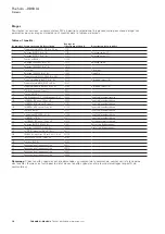
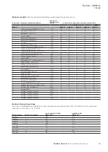
See tone table 2 for details of pre-selected tones.

ote: 

N

Closing more than one switch at a time will result 

in no tone being produced.


#

4.0 Operation

The sounder is available in various AC and DC input 

voltage versions.
For AC versions, 120Vac and 240Vac units comply with 

regulated supply limits, for all other AC versions, the 

nominal operating voltage is stated on the unit label and 

the supply voltage tolerance is ±10%.
For 12-48Vdc versions, the absolute input voltage range is 

11.0Vdc to 58.0Vdc.
The unit is fitted with a volume control which is 

positioned on the top face of the electronics assembly 

PCB. Maximum volume is obtained when this control is 

turned fully clockwise. When turned fully anti-clockwise 

the unit will emit no sound. For fire alarm use, if the 

control is not set to maximum volume, ensure the output 

from the horn meets the minimum level required by the 

relevant standards.

Warning:

 Do not attempt to turn the volume control past 

its limits of movement as this may cause damage to 

the unit.

Summary of Contents for DB3B UL

Page 1: ...The horn DB3B UL Technical manual...

Page 2: ...URPOSE OR MERCHANTABILITY OTHER THAN THOSE SPECIFICALLY SET OUT IN ANY EXISTING CONTRACT BETWEEN THE PARTIES ANY SUCH CONTRACT STATES THE ENTIRE OBLIGATION OF EATON THE CONTENTS OF THIS DOCUMENT SHALL...

Page 3: ...ard configuration wiring details Type 4 3 DC Version Up to 3 user selectable stages with 2 independantly powered stages Type 5 3 DC version Up to 3 stage with or without monitoring alternative configu...

Page 4: ...iv The horn DB3B UL TM261 April 2020 www eaton com...

Page 5: ...Ensure that only the correct listed or certified stopping plugs are used to blank off unused gland entry points and that the NEMA IP rating of the unit is maintained X MEDC recommend the use of a seal...

Page 6: ...es will produce no tone DC version 3 stage without monitoring wiring details Type 3 This type can be configured in a number of different ways depending on requirements Independent tone selection for a...

Page 7: ...s M1 M2 terminals ote N monitored terminals are not polarity dependent DC Version Up to 3 user selectable stages with 2 independantly powered stages Type 5 Connect up to 4 supply wires to the terminal...

Page 8: ...ation wiring details Type 7 Connect the positive ve and negative ve supply wires to the terminals as detailed in the wiring diagram When power is applied to the unit no tone will be produced initially...

Page 9: ...01101 Swedish Fire Alarm 20 Alt 554 440 Hz at 1 Hz 01100 Swedish Fire Alarm 21 Int 660 Hz at 7 8 Hz 01011 Swedish Fire Alarm 22 Int 2850 Hz 150 mS on 100 mS off 01010 Pelican Crossing 23 Sweep 800 970...

Page 10: ...T14 T10 T1 T8 T14 26 3x2850Hz pulses 0 5on 0 5off 1 5 off 00110 T14 T10 T1 T8 T14 27 Int 3100Hz 0 32s on 0 68s off 00101 T14 T10 T1 T8 T14 28 Continuous 1400Hz 00100 T14 T10 T1 T8 T14 29 Spare Custom...

Page 11: ...A Angle OSPL dBA Long Flare Version Horizontal Axis Reference 90 93 9 Reference 90 C 93 9 165 90 9 3 dBA 20 90 9 3 dBA 87 9 6 dBA 87 9 6 dBA 180 92 0 0 91 9 Long Flare Version Vertical Axis Reference...

Page 12: ...etal products However if abnormal or unusual environmental conditions occur due to plant damage or accident etc then visual inspection is recommended If the unit requires cleaning then only clean exte...

Page 13: ...0 Hz 122mA Special Applicaton 3 120 V ac 50 60 Hz 110 mA Regulated 4 220 230 Vac 50 60 Hz 63 mA Special Application 5 240 Vac 50 60 Hz 58 mA Regulated Note the DC special application version is suitab...

Page 14: ...der is intended for use in a safety system conforming to the requirements of IEC61508 UL has conducted a Failure Modes Effect and Diagnostic Analysis FMEDA of the DB3B Sounder against the requirements...

Page 15: ...for use in safety functions and the installation configuration overall validation maintenance and repair shall only be carried out by competent personnel observing all the manufacturer s conditions a...

Page 16: ...ard type 4 16 Version CC Jusqu 3 tages s lectionnables par l utilisateur avec 2 tages aliment s ind pendamment type 5 16 D tails du c blage version CC Jusqu trois tages avec ou sans surveillance confi...

Page 17: ...u certifi s doivent tre utilis s IX S assurer que seul les bouchons r pertori s corrects ou certifi s sont utilis s pour obturer les points d entr e des presse toupes inutilis s et que l indice IP NEM...

Page 18: ...teurs ne produira aucun son D tails du c blage version CC Trois tages sans surveillance type 3 Ce type peut tre configur de plusieurs mani res diff rentes en fonction des besoins La s lection ind pend...

Page 19: ...nes surveill es ne sont pas d pendantes de la polarit Version CC Jusqu 3 tages s lectionnables par l utilisateur avec 2 tages aliment s ind pendamment type 5 Branchez jusqu 4 fils d alimentation aux b...

Page 20: ...e d taill dans le sch ma de c blage L tage 1 est produit quand l alimentation est appliqu e entre les bornes du commun VE et VE de l tage 1 L tage 2 est produit quand l alimentation est appliqu e entr...

Page 21: ...12 48 V CC la gamme de tension d entr e absolue est de 11 0 V CC 58 0 V CC L unit est quip e d une commande de volume qui est positionn e sur la partie sup rieure de la platine du circuit imprim Le v...

Page 22: ...dant 0 1 S 440 Hz pendant 0 4 S 10001 Tonalit d incendie fran aise 16 Int 660 Hz 150 ms on 150 ms off 10000 Tonalit d incendie su doise 17 Int 660 Hz 1 8 sec on 1 8 sec off 01111 Tonalit d incendie su...

Page 23: ...T8 T14 16 Int 660 Hz 150 ms on 150 ms off 10000 T14 T10 T1 T8 T14 17 Int 660Hz 1 8 sec on 1 8 sec off 01111 T14 T10 T1 T8 T14 18 Int 660Hz 6 5 sec on 13 sec off 01110 T14 T10 T1 T8 T14 19 Continue 66...

Page 24: ...9 3 dBA 46 86 9 3 dBA 148 83 9 6 dBA 35 83 9 6 dBA 180 81 8 0 81 5 Axe vertical en version courte vas e R f rence 90 89 8 R f rence 90 89 8 143 86 8 3 dBA 47 86 8 3 dBA 150 83 8 3 dBA 35 83 8 6 dBA 18...

Page 25: ...es Toutefois si des conditions environnementales anormales ou inhabituelles se produisent en raison de dommages l installation ou d accident etc alors un contr le visuel est recommand Si l unit n cess...

Page 26: ...sez au minimum des c bles class s 105 C 6 Avertissement sur les unit s peintes pour viter l accumulation de charges lectrostatiques nettoyer le bo tier avec un chiffon humide 7 Avertissement afin de r...

Page 27: ...ettre l int grit de s curit de l quipement valu 1 L utilisateur est tenu de se conformer aux exigences nonc es dans la documentation utilisateur fournie par le fabricant ce Manuel de s curit et Manuel...

Page 28: ...n contained in this document and to prices are reserved so are errors and omissions Only order confirmations and technical documentation by Eaton is binding Photos and pictures also do not warrant a s...

Reviews: