5 Operation
5.5 Commissioning with control signal terminals (default settings)
112
DC1-S…20…, DC1-S…OE1 Variable Frequency Drives
05/21 MN040058EN
www.eaton.com
5.5 Commissioning with control signal terminals (default settings)
DC1-S… variable frequency drives come pre-configured for their rated mains
voltage and motor output. Once the corresponding motor and mains voltage
are connected, these drives allow for direct operation via their control signal
terminals.
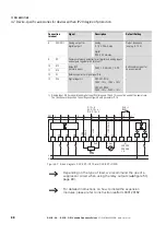
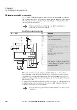
Simplified connecting example
The potentiometer should have a fixed resistance (connection to the control
terminals 5 and 7) of at least 1 k
Ω
and up to a maximum of 10 k
Ω
.
A standard fixed resistance of 4.7 k
Ω
is recommended.
When the specified supply voltage is applied at the mains connection
terminals (L1/L, L2/N), the switched-mode power supply unit (SMPS) in the
internal DC link will be used to generate the control voltage and light up the
7-segment LED display (
StoP
). At this point, the variable frequency drive will
be ready for operation (correct operating status) and in Stop mode.
The start enable signal is sent by applying the +24 V voltage on terminal 1:
FWD = Start.
DC1-S… with IP20 degree of protection
Pin
Designation
L1/L
Single-phase mains connection
L2/N
Ground connection
1
Control v24 V (output, maximum 100 mA)
2
FWD, Start release clockwise rotating field
3
U
Connection for a single-phase AC motor
V
CO
5
Reference v10 V (Output, maximum 10 mA)
6
Frequency reference value f-Set (Input 0 – +10 V)
7
Reference potential (0 V)
V
U
M
3 ~
6
7
5
1
2
3
+24 V
FWD
0...+10 V
0 V
+10 V
L1/L L2/N
L
N
L1
L2
f-Soll
PE
PE
→
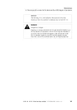
Make sure that the enable contact FWD is open before
switching on the mains voltage.
Summary of Contents for DC1-S1011NB-A20CE1 1
Page 4: ......

