Effective
10
/00
Page 15
IL 33-K2C-3
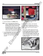
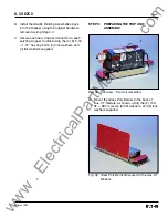
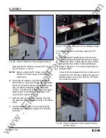
Fig. 22 Routing of the HV Wires
D. Carefully lay the Breaker on its left side.
E. Temporarily set the CPT Assembly on the right
Breaker Side Plate. Route the CPT Harness to
the X1 and X2 terminals of the Breaker
Mounted CPT. Mark and cut the CPT Harness
to an appropriate length. Strip an appropriate
length of insulation and attach a .138" ring
terminal to each wire of the CPT Harness.
Connect the CPT Harness to the X1 and X2
terminals of the CPT.
F.
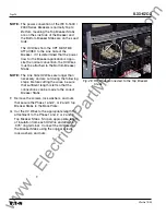
With the CPT still temporarily set on the right
Breaker Side Plate, route the Load Side HV
Wires to the “H” terminals of the Breaker
Mounted CPT. Mark and cut the HV Wires to
an appropriate length. Strip an appropriate
length of insulation and attach a .138" ring
terminal to each wire of the HV Wire. Attach
the HV Wires to the CPT terminals to achieve
the required voltage. (See Table 3.)
Table 3
CPT Voltage Taps
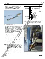
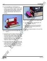
Fig. 23 CPT Harness and HV Wires connected to
the CPT
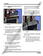
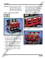
G. Align the holes in the CPT Assembly with the
holes in the DTA Assembly as shown. Secure
the left side of the CPT Mounting Plate to the
DTA Mounting Angle, as shown, using the (1)
.164-32 × .625" screw, (2) flat washer, (1) lock
washer, and (1) nut supplied.
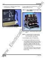
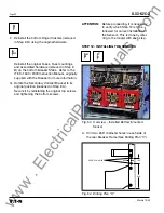
H. Align the holes in the CPT Insulation Barrier
Assembly with the holes in the CPT Assembly
and the DTA Assembly. Secure the Insulation
Barrier Assembly and the right side of the CPT
Assembly to the DTA Assembly, as shown,
using the (2) .164-32 × .625" screws, (4) flat
washers, (2) lock washers, and (2) nuts
supplied.
Voltage Required
CPT Terminals Used
480 Volt Circuit
H1 & H4
240 Volt Circuit
H1 & H3
208 Volt Circuit
H1 & H2
www
. ElectricalPartManuals
. com


