Effective
10
/00
IL 33-K2C-3
Page 16
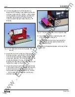
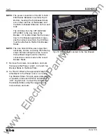
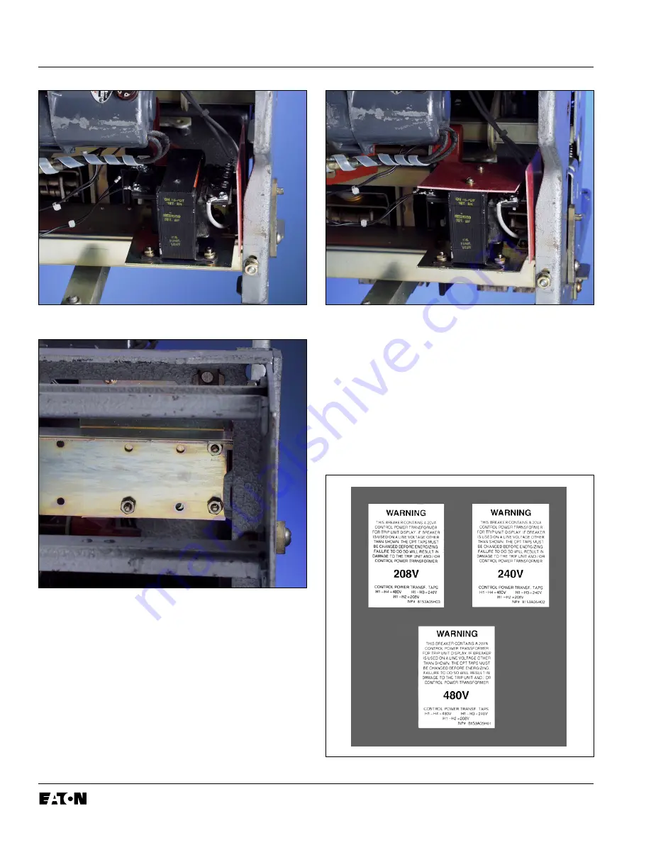
Fig. 24 CPT Mounted to the DTA Assembly
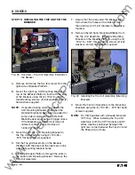
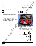
Fig. 25 CPT Mounting Screw Location
I.
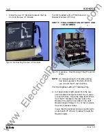
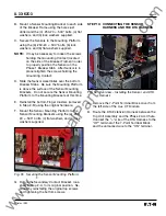
Attach the Glass Poly Insulation Plate to the
top of the CPT, as shown, using the (2) .138-20
× .375" thread cutting screws, (2) lock washers,
and (2) flat washers supplied.
Fig. 26 Insulation Plate Mounted to the CPT
J. Tighten the hardware that secures the DTA
Assembly to the Breaker.
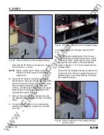
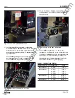
K. Attach the appropriate CPT Voltage Label in a
clearly visible position on the front of the
Breaker. Three (3) labels are included with the
CPT Kit, one (1) for 480
Volt, one (1)
for 240 Volt,
and one (1) for 208
Volt
systems.
Fig. 27 Supplied CPT Voltage Labels
www
. ElectricalPartManuals
. com


