Effective
10
/00
Page 17
IL 33-K2C-3
STEP 7:
FINAL DTA AND RESET
INSTALLATION AND ADJUSTMENT
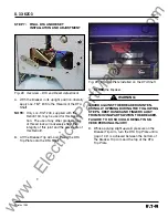
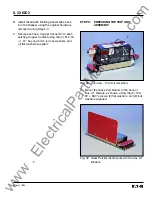
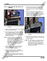
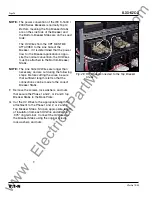
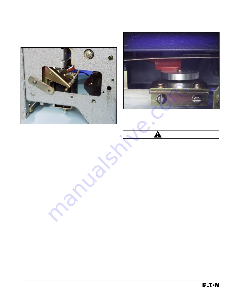
Fig. 29 DTA Trip Plate Installed on the DTA Shaft
C.
CLOSE
the Breaker.
WARNING:
GUARD AGAINST THE BREAKER UNINTEN-
TIONALLY OPENING DURING THE FOLLOWING
STEPS. KEEP HANDS AND FINGERS AWAY
FROM MOVING PARTS WITHIN THE BREAKER.
FAILURE TO DO SO COULD RESULT IN SE-
VERE PERSONAL INJURY.
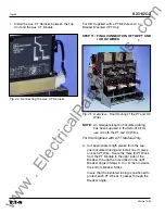
D. While applying slight upward pressure on the
Breaker Trip Arm, turn the DTA Trip Plate until a
gap of .06" is achieved between the bottom of
the Breaker Trip Arm and the top of the DTA
Trip Plate.
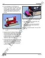
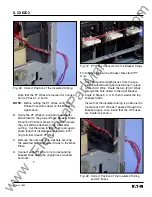
Fig. 28 Overview – DTA and Reset Adjustment
A. With the Breaker in its upright position, liberally
apply Loc-Tite
®
243 to the threads of the DTA
Shaft.
NOTE:
Only Loc-Tite
®
243, supplied with the
Retrofit Kit, may be used for this applica-
tion. The use of any other grade or type
of thread lock will adversely effect the
integrity of this joint and the service life of
this Retrofit.
B. Lift the Breaker Trip Arm and thread the DTA
Trip Plate onto the DTA Shaft.
www
. ElectricalPartManuals
. com


