Effective
10
/00
Page 21
IL 33-K2C-3
B. Install the Glastic Molding Assemblies back
into the Breaker using the original hardware
removed during Step 2-C.
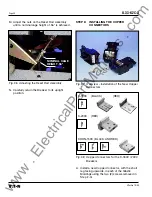
C. Secure each new Copper Connector to each
existing Copper Contact using the (4) .312-18
× 1.12" hex cap bolts, (4) lock washers, and
(4) flat washers supplied.
STEP 9:
PREPARING THE TRIP UNIT
ASSEMBLY
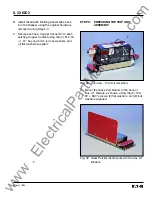
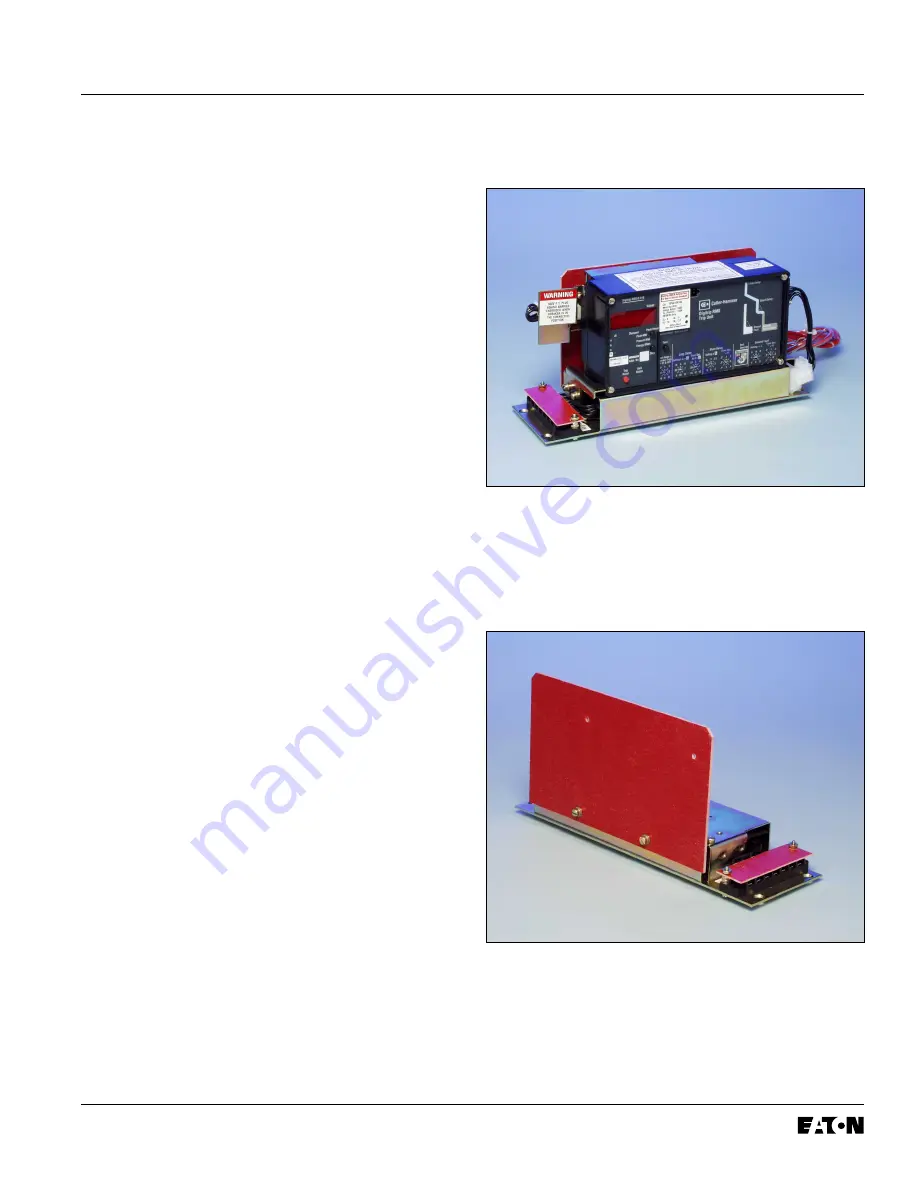
Fig. 38 Overview – Trip Unit Assembly
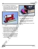
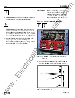
A. Mount the Glass Poly Barrier to the back of
Aux. CT Module, as shown, using the (2) .190-
32 × .380" screws, (2) flat washers, and (2) lock
washers supplied.
Fig. 39 Glass Poly Barrier Mounted to the Aux. CT
Module
www
. ElectricalPartManuals
. com


